Toyota CH-R Service Manual: Low Power Supply Voltage Malfunction (C1241)
DESCRIPTION
If a malfunction is detected in the power supply circuit, the skid control ECU (brake actuator assembly) stores this DTC and the fail-safe function prohibits ABS operation. This DTC is stored when the +BS terminal voltage meets one of the DTC detection conditions due to a malfunction in the power supply or charging circuit such as the battery or alternator circuit, etc. The DTC is cleared when the +BS terminal voltage returns to normal.
|
DTC No. |
Detection Item |
DTC Detection Condition |
Trouble Area |
|---|---|---|---|
|
C1241 |
Low Power Supply Voltage Malfunction |
Any of the following is detected:
|
|
*: The skid control ECU (brake actuator assembly) monitors the resistance of the power source line at the +BS terminal. A malfunction is detected when an abnormality occurs in the +BS terminal wire harness or its connection and the skid control ECU (brake actuator assembly) determines that the wiring resistance at the +BS terminal exceeds the standard resistance.
DTC Detection Conditions: C1241|
Vehicle Condition |
|||||
|---|---|---|---|---|---|
|
Pattern 1 |
Pattern 2 |
Pattern 3 |
Pattern 4 |
||
|
Diagnosis Condition |
- |
- |
- |
- |
- |
|
Malfunction Status |
The vehicle speed is 6 km/h (4 mph) or more and the +BS terminal voltage (soft low voltage) is less than 9.6 V. |
○ |
- |
- |
- |
|
The vehicle speed is 6 km/h (4 mph) or more and the +BS terminal voltage (hard low voltage) is less than 6.9 V. |
- |
○ |
- |
- |
|
|
The vehicle speed is 15 km/h (9 mph) or more, the +BS terminal voltage is 9.6 V or more, the skid control ECU (brake actuator assembly) turns on more than one valve at the same time within a short period of time and the valve relay supply voltage drop exceeds the threshold.* |
- |
- |
○ |
- |
|
|
The +BS terminal voltage is less than 6.7 V and the skid control ECU (brake actuator assembly) judges that power supply voltage is abnormal. |
- |
- |
- |
○ |
|
|
Detection Time |
1 second or more |
1 second or more |
- |
0.06 seconds or more |
|
|
Number of Trips |
1 trip |
1 trip |
1 trip |
1 trip |
|
HINT:
DTC will be output when conditions for either of the patterns in the table above are met.
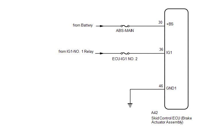
WIRING DIAGRAM
CAUTION / NOTICE / HINT
NOTICE:
- When replacing the skid control ECU (brake actuator assembly), perform
system variant learning.
Click here
.gif)
- Inspect the fuses for circuits related to this system before performing the following procedure.
PROCEDURE
|
1. |
CHECK BATTERY |
(a) Check the battery voltage.
Standard Voltage:
11 to 14 V
| NG | .gif) |
CHECK OR REPLACE CHARGING SYSTEM COMPONENT OR BATTERY |
|
.gif)
|
2. |
CHECK HARNESS AND CONNECTOR (POWER SOURCE TERMINAL) |
|
(a) Make sure that there is no looseness at the locking part and the connecting part of the connector. |
|
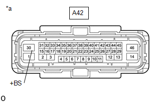
(b) Disconnect the A42 skid control ECU (brake actuator assembly) connector.
(c) Measure the voltage according to the value(s) in the table below.
Standard Voltage:
|
Tester Connection |
Condition |
Specified Condition |
|---|---|---|
|
A42-30 (+BS) - Body ground |
Always |
11 to 14 V |
| NG | |
REPAIR OR REPLACE HARNESS OR CONNECTOR (IG1 CIRCUIT) |
|
|
3. |
CHECK HARNESS AND CONNECTOR (POWER SOURCE (IG1) TERMINAL) |
|
(a) Disconnect the A42 skid control ECU (brake actuator assembly) connector. |
|
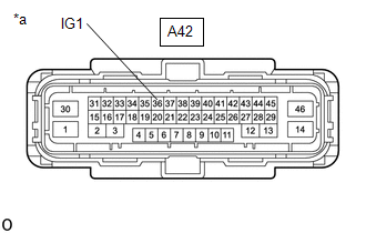
(b) Measure the voltage according to the value(s) in the table below.
Standard Voltage:
|
Tester Connection |
Condition |
Specified Condition |
|---|---|---|
|
A42-36 (IG1) - Body ground |
Ignition switch ON |
11 to 14 V |
| NG | |
REPAIR OR REPLACE HARNESS OR CONNECTOR (POWER SOURCE CIRCUIT) |
|
|
4. |
CHECK HARNESS AND CONNECTOR (GND1 TERMINAL) |
|
(a) Turn the ignition switch off. |
|
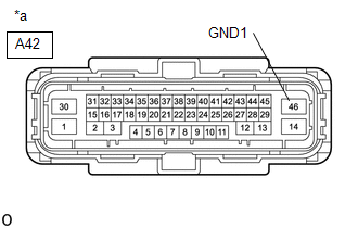
(b) Measure the resistance according to the value(s) in the table below.
Standard Resistance:
|
Tester Connection |
Condition |
Specified Condition |
|---|---|---|
|
A42-46 (GND1) - Body ground |
Always |
Below 1 Ω |
| NG | |
REPAIR OR REPLACE HARNESS OR CONNECTOR (GND1 CIRCUIT) |
|
|
5. |
RECONFIRM DTC |
(a) Reconnect the A42 skid control ECU (brake actuator assembly) connector.
(b) Clear the DTCs.
Click here
(c) Turn the ignition switch off.
(d) Start the engine.
(e) Perform a road test.
(f) Check if the same DTC is output.
Click here
|
Result |
Proceed to |
|---|---|
|
DTC C1241 is not output. |
A |
|
DTC C1241 is output. |
B |
HINT:
If troubleshooting has been carried out according to Problem Symptoms Table, refer back to the table and proceed to the next step before replacing parts.
Click here
| A | |
USE SIMULATION METHOD TO CHECK
|
| B | |
REPLACE BRAKE ACTUATOR ASSEMBLY |
 Speed Sensor Rotor Faulty (C1237)
DESCRIPTION
The skid control ECU (brake actuator assembly) measures the speed of each wheel
by receiving signals from each speed sensor.
These signals are used for recognizing that all four wheels ...
 Acceleration Sensor Stuck Malfunction (C1243,C1245)
DESCRIPTION
The skid control ECU (brake actuator assembly) receives signals from the yaw
rate and acceleration sensor (airbag sensor assembly) via CAN communication.
The airbag sensor assembly has ...
Other materials:
Toyota CH-R Service Manual > Audio And Visual System(for Radio Receiver Type): How To Proceed With Troubleshooting
CAUTION / NOTICE / HINT
HINT:
Use the following procedure to troubleshoot the audio and visual system.
PROCEDURE
1.
VEHICLE BROUGHT TO WORKSHOP
NEXT
2.
CUSTOMER PROBLEM ANALYS ...
Toyota CH-R Service Manual > Audio And Visual System(for Radio And Display Type): Satellite Radio Broadcast cannot be Selected or After Selecting Broadcast, Broadcast
cannot be Added into Memory
CAUTION / NOTICE / HINT
NOTICE:
Some satellite radio broadcasts require payment. A contract must be made between
a satellite radio company and the user. If the contract expires, it will not be
possible to listen to the broadcast.
PROCEDURE
1.
CHECK SATELLITE RADIO
...
Toyota C-HR (AX20) 2023-2026 Owner's Manual
Toyota CH-R Owners Manual
- For safety and security
- Instrument cluster
- Operation of each component
- Driving
- Interior features
- Maintenance and care
- When trouble arises
- Vehicle specifications
- For owners
Toyota CH-R Service Manual
- Introduction
- Maintenance
- Audio / Video
- Cellular Communication
- Navigation / Multi Info Display
- Park Assist / Monitoring
- Brake (front)
- Brake (rear)
- Brake Control / Dynamic Control Systems
- Brake System (other)
- Parking Brake
- Axle And Differential
- Drive Shaft / Propeller Shaft
- K114 Cvt
- 3zr-fae Battery / Charging
- Networking
- Power Distribution
- Power Assist Systems
- Steering Column
- Steering Gear / Linkage
- Alignment / Handling Diagnosis
- Front Suspension
- Rear Suspension
- Tire / Wheel
- Tire Pressure Monitoring
- Door / Hatch
- Exterior Panels / Trim
- Horn
- Lighting (ext)
- Mirror (ext)
- Window / Glass
- Wiper / Washer
- Door Lock
- Heating / Air Conditioning
- Interior Panels / Trim
- Lighting (int)
- Meter / Gauge / Display
- Mirror (int)
- Power Outlets (int)
- Pre-collision
- Seat
- Seat Belt
- Supplemental Restraint Systems
- Theft Deterrent / Keyless Entry

0.0073