Toyota CH-R Service Manual: Disassembly
DISASSEMBLY
CAUTION / NOTICE / HINT
The necessary procedures (adjustment, calibration, initialization or registration) that must be performed after parts are removed and installed, or replaced during the rear door removal/installation are shown below.
Necessary Procedures After Parts Removed/Installed/Replaced|
Replaced Part or Performed Procedure |
Necessary Procedure |
Effects / Inoperative when not performed |
Link |
|---|---|---|---|
|
Disconnect cable from negative battery terminal |
Initialize back door lock |
Power door lock control system |
|
|
Memorize steering angle neutral point |
Lane departure alert system (w/ Steering Control) |
|
|
|
Pre-collision system |
|||
|
Initialize Power Window Control System |
|
|
HINT:
- Use the same procedure for the RH side and LH side.
- The following procedure is for the LH side.
PROCEDURE
1. PRECAUTION
NOTICE:
After turning the ignition switch off, waiting time may be required before disconnecting the cable from the negative (-) battery terminal. Therefore, make sure to read the disconnecting the cable from the negative (-) battery terminal notices before proceeding with work.
Click here
.gif)
2. DISCONNECT CABLE FROM NEGATIVE BATTERY TERMINAL
Click here
NOTICE:
When disconnecting the cable, some systems need to be initialized after the cable is reconnected.
Click here
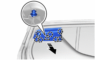
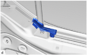
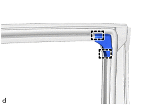
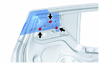
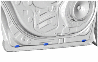
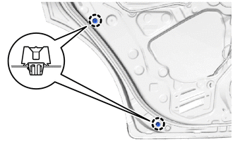
3. REMOVE REAR DOOR REAR FRAME BRACKET
(a) Disengage the claws and clip to remove the rear door rear frame bracket as shown in the illustration.
.png) |
Remove in this Direction |
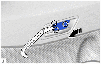
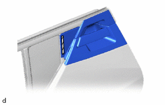
4. REMOVE REAR DOOR INSIDE HANDLE BEZEL PLUG
(a) Using a moulding remover A, disengage the claws to remove the rear door inside handle bezel plug as shown in the illustration.
|
|
Remove in this Direction |
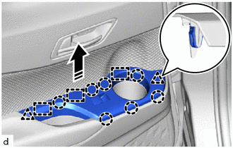
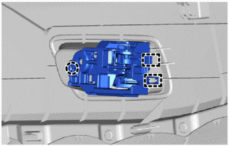
5. REMOVE REAR POWER WINDOW REGULATOR SWITCH ASSEMBLY WITH REAR DOOR ARMREST BASE UPPER PANEL
(a) Disengage the claws, clips and guides as shown in the illustration.
|
|
Remove in this Direction |
|
(b) Disconnect the connector to remove the rear power window regulator switch assembly with rear door armrest base upper panel. |
|
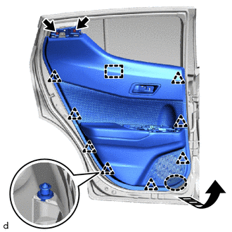
6. REMOVE REAR DOOR TRIM BOARD SUB-ASSEMBLY
|
(a) Remove the 3 screws. |
|
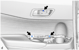
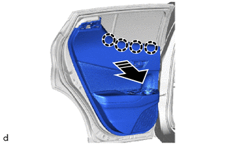
(b) Remove the 2 screws.
.png) |
Place Hands Here |
|
|
Remove in this Direction |
(c) Disengage the clips and guide as shown in the illustration.
(d) Disengage the claws as shown in the illustration.
|
|
Remove in this Direction |
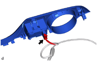
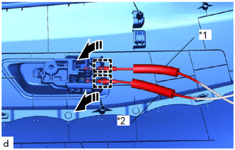
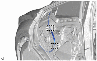
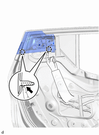
(e) Disengage the guides to disconnect the rear door inside locking cable assembly and rear door lock remote control cable assembly to remove the rear door trim board sub-assembly as shown in the illustration.
|
*1 |
Rear Door Inside Locking Cable Assembly |
|
*2 |
Rear Door Lock Remote Control Cable Assembly |
|
|
Remove in this Direction |
7. REMOVE REAR DOOR INSIDE HANDLE SUB-ASSEMBLY
|
(a) Disengage the claw and guides to remove the front door inside handle sub-assembly. |
|
8. REMOVE REAR DOOR BELT REAR SEAL
|
(a) Remove the rear door belt rear seal. |
|
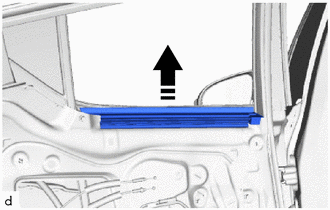
9. REMOVE REAR DOOR GLASS INNER WEATHERSTRIP
(a) Remove the rear door glass inner weatherstrip with the rear door belt seal as shown in the illustration.
|
|
Remove in this Direction |
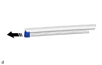
10. REMOVE REAR DOOR BELT SEAL
(a) Remove the rear door belt seal from the rear door glass inner weatherstrip as shown in the illustration.
|
|
Remove in this Direction |
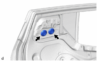
11. REMOVE HOLE PLUG
|
(a) Remove the 2 hole plugs. |
|
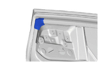
12. REMOVE NO. 2 REAR DOOR FRAME GARNISH
|
(a) Remove the No. 2 rear door frame garnish. |
|
13. REMOVE REAR DOOR TRIM BRACKET
|
(a) Remove the 2 screws and rear door trim bracket. |
|
14. REMOVE REAR DOOR INSIDE PANEL REINFORCE SUB-ASSEMBLY (w/ Rear Seat Side Airbag)
|
(a) Remove the 4 screws and rear door inside panel reinforce sub-assembly. |
|
15. REMOVE REAR DOOR SERVICE HOLE COVER
(a) Remove the rear door service hole cover.
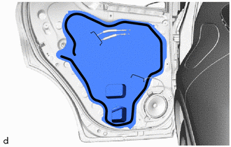
 |
Butyl Tape |
HINT:
Remove any remaining butyl tape from the rear door panel.
16. REMOVE NO. 2 SEPARATOR DOOR STIFFENER CUSHION (w/ Rear Seat Side Airbag)
(a) Remove the 2 bolts.
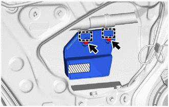
.png) |
Double-sided Tape |
(b) Peel back the double-sided tape.
(c) Disengage the guides to remove the No. 2 separator door stiffener cushion.
NOTICE:
Remove any remaining double-sided tape from the rear door panel.
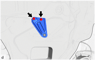
17. REMOVE REAR DOOR CUSHION (w/ Rear Seat Side Airbag)
|
(a) Remove the 2 bolts. |
|
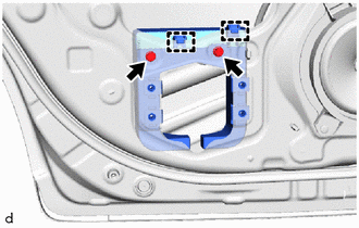
(b) Disengage the hooks to remove the rear door cushion.
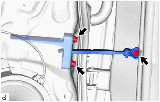
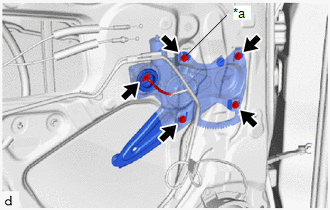
18. REMOVE REAR DOOR CHECK ASSEMBLY
|
(a) Remove the 3 bolts and rear door check assembly. |
|
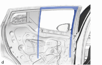
19. REMOVE REAR DOOR WEATHERSTRIP
(a) Using a clip remover, disengage the clip (A) and other clips.
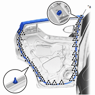
|
*a |
Clip (A) |
|
|
Double-sided Tape |
(b) Remove the double-sided tape and rear door weatherstrip.
NOTICE:
Remove any remaining double-sided tape from the rear door panel.
20. REMOVE REAR DOOR WINDOW REAR LOWER FRAME SUB-ASSEMBLY
|
(a) Remove the screw and 2 bolts. |
|
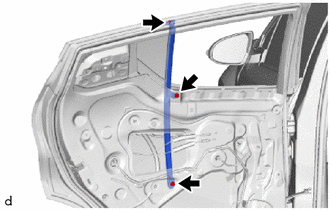
(b) Remove the rear door window rear lower frame sub-assembly from the rear door glass run.
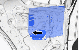
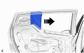
21. REMOVE REAR DOOR GLASS SUB-ASSEMBLY
|
(a) Disengage the rear door glass sub-assembly from the rear door window regulator sub-assembly as shown in the illustration. NOTICE: After separating the rear door glass sub-assembly, do not allow it to fall. |
|
(b) Remove the rear door glass sub-assembly as shown in the illustration.
NOTICE:
Do not damage the rear door glass sub-assembly.
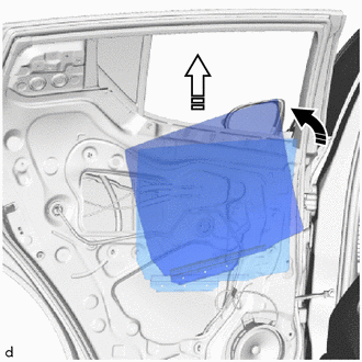
|
|
Remove in this Direction (1) |
.png) |
Remove in this Direction (2) |
22. REMOVE REAR DOOR FRAME GARNISH
|
(a) Disengage the guides to remove the rear door frame garnish. |
|
23. REMOVE REAR DOOR GLASS RUN
|
(a) Remove the rear door glass run. |
|
24. REMOVE REAR DOOR WINDOW REGULATOR ASSEMBLY
|
(a) Disconnect the connector. |
|
(b) Loosen the temporary bolt.
NOTICE:
Do not remove the temporary bolt. If the temporary bolt is removed, the rear door window regulator assembly may fall and cause damage.
(c) Remove the 3 bolts and rear door window regulator assembly.
(d) Remove the temporary bolt from the rear door window regulator assembly.
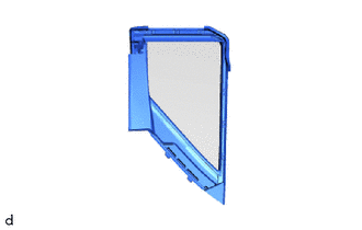
25. REMOVE REAR DOOR QUARTER WINDOW GLASS
(a) Remove the rear door quarter window glass with rear door quarter window weatherstrip as shown in the illustration.
|
|
Remove in this Direction |
26. REMOVE REAR DOOR QUARTER WINDOW WEATHERSTRIP
|
(a) Remove the rear door quarter window weatherstrip from the rear door quarter window glass. |
|
27. REMOVE REAR DOOR BELT MOULDING ASSEMBLY
Click here
28. REMOVE REAR DOOR OUTSIDE HANDLE ASSEMBLY
|
(a) Disconnect the No. 1 rear door lock remote control cable assembly from the clamps. |
|
|
(b) Remove the 3 bolts. |
|
(c) Peel back the double-sided tape.
|
|
Double-sided Tape |
(d) Disengage the claws from the rear door service hole as shown in the illustration to separate the rear door outside handle assembly together with the rear door outside handle cover as a single unit.
.png) |
Push |
CAUTION:
Be careful not to cut your hands or fingers on the edge of the rear door panel.
HINT:
If your hands cannot fit, use a tool such as a screwdriver with its tip wrapped in protective tape to disengage the claws.
|
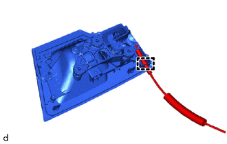
(e) Disengage the guide to disconnect the No. 1 rear door lock remote control cable assembly to remove the rear door outside handle assembly with the rear door outside handle cover. NOTICE: Remove any remaining double-sided tape from the rear door panel. |
|
29. REMOVE REAR DOOR OUTSIDE HANDLE COVER
|
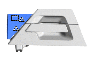
(a) Disengage the clips and guide to remove the rear door outside handle cover. |
|
30. REMOVE REAR DOOR OUTSIDE HANDLE SEAL
|
(a) Remove the 2 rear door outside handle seals. |
|
31. REMOVE REAR DOOR LOCK WITH MOTOR ASSEMBLY
Click here
32. REMOVE REAR DOOR DUST PROOF SEAL
|
(a) Remove the 3 rear door dust proof seals. |
|
33. REMOVE REAR SPEAKER ASSEMBLY
Click here
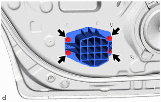
34. REMOVE REAR DOOR PANEL CUSHION
|
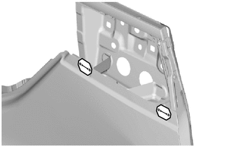
(a) Disengage the claws to remove the 2 rear door panel cushions. |
|
35. REMOVE REAR DOOR OUTSIDE MOULDING SUB-ASSEMBLY
Click here
36. REMOVE REAR DOOR OUTSIDE MOULDING
Click here
37. REMOVE REAR DOOR UPPER WINDOW FRAME MOULDING
Click here
38. REMOVE REAR DOOR REAR WINDOW FRAME MOULDING
Click here
39. REMOVE REAR DOOR LOWER OUTSIDE STRIPE
Click here
40. REMOVE REAR DOOR OUTSIDE STRIPE
Click here
 Components
COMPONENTS
ILLUSTRATION
*1
REAR DOOR BELT REAR SEAL
*2
REAR DOOR BELT SEAL
*3
REAR DOOR GLASS INNER WEATHERSTRIP
...
 Adjustment
ADJUSTMENT
CAUTION / NOTICE / HINT
*a
Centering Bolt
*b
Standard Bolt
HINT:
Use the same procedure for the RH side and LH side. ...
Other materials:
Toyota CH-R Service Manual > Terms: Abbreviations Used In Manual
ABBREVIATIONS USED IN MANUAL
Abbreviation
Meaning
ABS
Anti-Lock Brake System
A/C
Air Conditioner
AC
Alternating Current
ACC
Accessory
ACIS
...
Toyota CH-R Service Manual > Key Reminder Warning System: Data List / Active Test
DATA LIST / ACTIVE TEST
DATA LIST
HINT:
Using the Techstream to read the Data List allows the values or states of switches,
sensors, actuators and other items to be read without removing any parts. This non-intrusive
inspection can be very useful because intermittent conditions or signals may ...
Toyota C-HR (AX20) 2023-2026 Owner's Manual
Toyota CH-R Owners Manual
- For safety and security
- Instrument cluster
- Operation of each component
- Driving
- Interior features
- Maintenance and care
- When trouble arises
- Vehicle specifications
- For owners
Toyota CH-R Service Manual
- Introduction
- Maintenance
- Audio / Video
- Cellular Communication
- Navigation / Multi Info Display
- Park Assist / Monitoring
- Brake (front)
- Brake (rear)
- Brake Control / Dynamic Control Systems
- Brake System (other)
- Parking Brake
- Axle And Differential
- Drive Shaft / Propeller Shaft
- K114 Cvt
- 3zr-fae Battery / Charging
- Networking
- Power Distribution
- Power Assist Systems
- Steering Column
- Steering Gear / Linkage
- Alignment / Handling Diagnosis
- Front Suspension
- Rear Suspension
- Tire / Wheel
- Tire Pressure Monitoring
- Door / Hatch
- Exterior Panels / Trim
- Horn
- Lighting (ext)
- Mirror (ext)
- Window / Glass
- Wiper / Washer
- Door Lock
- Heating / Air Conditioning
- Interior Panels / Trim
- Lighting (int)
- Meter / Gauge / Display
- Mirror (int)
- Power Outlets (int)
- Pre-collision
- Seat
- Seat Belt
- Supplemental Restraint Systems
- Theft Deterrent / Keyless Entry

0.0082