Toyota CH-R Service Manual: Adjustment
ADJUSTMENT
CAUTION / NOTICE / HINT
.png)
|
*a |
Centering Bolt |
|
*b |
Standard Bolt |
HINT:
- Use the same procedure for the RH side and LH side.
- The following procedure is for the LH side.
- Centering bolts are used to install the door hinges to the vehicle body and door. The door cannot be adjusted with the centering bolts installed. Substitute the centering bolts with standard bolts when making adjustments.
- The specified torque for standard bolts is shown in the standard bolt
chart.
Click here
.gif)
PROCEDURE
1. INSPECT REAR DOOR PANEL SUB-ASSEMBLY
(a) Check that the clearance measurements of areas "A" to "W" are within the standard ranges.
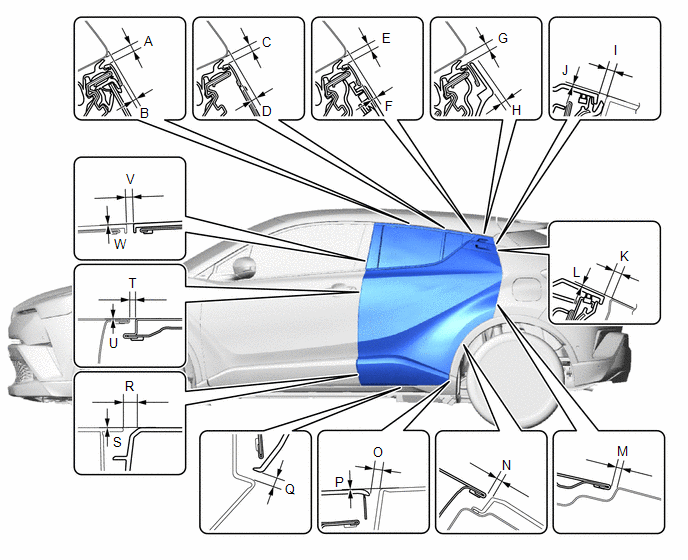 Standard Clearance
|
Area |
Measurement |
Area |
Measurement |
|---|---|---|---|
|
A |
3.3 to 6.7 mm (0.130 to 0.264 in.) |
B |
0.9 to 4.9 mm (0.035 to 0.193 in.) |
|
C |
3.3 to 6.7 mm (0.130 to 0.264 in.) |
D |
1.8 to 5.8 mm (0.071 to 0.228 in.) |
|
E |
3.3 to 6.7 mm (0.130 to 0.264 in.) |
F |
2.5 to 6.5 mm (0.098 to 0.256 in.) |
|
G |
3.3 to 6.7 mm (0.130 to 0.264 in.) |
H |
2.3 mm (0.091 in.) |
|
I |
3.3 to 7.3 mm (0.130 to 0.287 in.) |
J |
1.0 mm (0.039 in.) |
|
K |
2.6 to 6.6 mm (0.102 to 0.260 in.) |
L |
0.7 mm (0.028 in.) |
|
M |
2.6 to 5.6 mm (0.102 to 0.220 in.) |
N |
2.1 to 6.1 mm (0.083 to 0.240 in.) |
|
O |
3.3 to 8.3 mm (0.130 to 0.327 in.) |
P |
-2.5 to 2.5 mm (-0.098 to 0.098 in.) |
|
Q |
3.5 to 8.5 mm (0.138 to 0.335 in.) |
R |
7.5 to 11.5 mm (0.295 to 0.453 in.) |
|
S |
-2.0 to 2.0 mm (-0.079 to 0.079 in.) |
T |
2.9 to 5.3 mm (0.114 to 0.209 in.) |
|
U |
-1.2 to 1.2 mm (-0.047 to 0.047 in.) |
V |
2.4 to 6.4 mm (0.094 to 0.252 in.) |
|
W |
-2.0 to 2.0 mm (-0.079 to 0.079 in.) |
- |
- |
2. ADJUST REAR DOOR PANEL SUB-ASSEMBLY
|
(a) Using SST, loosen the 4 hinge bolts on the vehicle body and adjust the door position. SST: 09812-00010 |
|
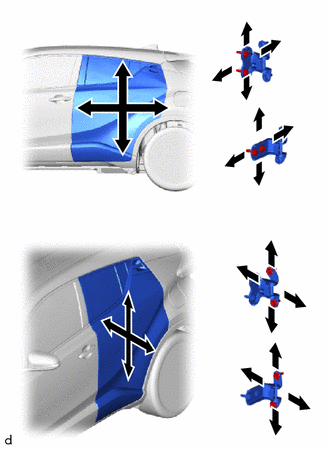
(b) Tighten the 4 hinge bolts on the vehicle body after adjustment.
Torque:
26 N·m {265 kgf·cm, 19 ft·lbf}
(c) Loosen the 4 hinge bolts on the door and adjust the door position.
(d) Tighten the 4 hinge bolts on the door after adjustment.
Torque:
for TMMT Made :
26 N·m {265 kgf·cm, 19 ft·lbf}
for TMC Made :
21 N·m {214 kgf·cm, 15 ft·lbf}
|
(e) Using a T40 "TORX" socket wrench, slightly loosen the 2 striker mounting screws. |
|
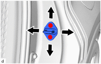
(f) Using a brass bar and a hammer, hit the striker to adjust its position.
(g) Using a T40 "TORX" socket wrench, tighten the 2 striker mounting screws after adjustment.
Torque:
23 N·m {235 kgf·cm, 17 ft·lbf}
 Disassembly
DISASSEMBLY
CAUTION / NOTICE / HINT
The necessary procedures (adjustment, calibration, initialization or registration)
that must be performed after parts are removed and installed, or replaced dur ...
 Reassembly
REASSEMBLY
CAUTION / NOTICE / HINT
HINT:
Use the same procedure for the RH side and LH side.
The following procedure is for the LH side.
PROCEDURE
1. INSTALL REAR DOOR OUTSIDE S ...
Other materials:
Toyota CH-R Service Manual > Vehicle Stability Control System: Slip Indicator Light Remains ON
DESCRIPTION
The skid control ECU (brake actuator assembly) is connected to the combination
meter assembly via CAN communication.
The slip indicator light blinks during VSC and/or TRAC operation.
If a malfunction is detected, the slip indicator light comes on to warn the driver.
Click here
...
Toyota CH-R Service Manual > Blind Spot Monitor System: Data List / Active Test
DATA LIST / ACTIVE TEST
DATA LIST
NOTICE:
In the table below, the values listed under "Normal Condition" are reference
values. Do not depend solely on these reference values when deciding whether a part
is faulty or not.
HINT:
Using the Techstream to read the Data List allows the ...
Toyota C-HR (AX20) 2023-2026 Owner's Manual
Toyota CH-R Owners Manual
- For safety and security
- Instrument cluster
- Operation of each component
- Driving
- Interior features
- Maintenance and care
- When trouble arises
- Vehicle specifications
- For owners
Toyota CH-R Service Manual
- Introduction
- Maintenance
- Audio / Video
- Cellular Communication
- Navigation / Multi Info Display
- Park Assist / Monitoring
- Brake (front)
- Brake (rear)
- Brake Control / Dynamic Control Systems
- Brake System (other)
- Parking Brake
- Axle And Differential
- Drive Shaft / Propeller Shaft
- K114 Cvt
- 3zr-fae Battery / Charging
- Networking
- Power Distribution
- Power Assist Systems
- Steering Column
- Steering Gear / Linkage
- Alignment / Handling Diagnosis
- Front Suspension
- Rear Suspension
- Tire / Wheel
- Tire Pressure Monitoring
- Door / Hatch
- Exterior Panels / Trim
- Horn
- Lighting (ext)
- Mirror (ext)
- Window / Glass
- Wiper / Washer
- Door Lock
- Heating / Air Conditioning
- Interior Panels / Trim
- Lighting (int)
- Meter / Gauge / Display
- Mirror (int)
- Power Outlets (int)
- Pre-collision
- Seat
- Seat Belt
- Supplemental Restraint Systems
- Theft Deterrent / Keyless Entry

0.0085