Toyota CH-R Service Manual: Yaw Rate Sensor (C1234,C1472,C1474)
DESCRIPTION
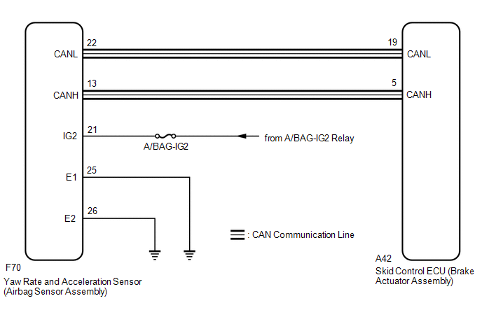
The skid control ECU (brake actuator assembly) receives signals from the yaw rate and acceleration sensor (airbag sensor assembly) via CAN communication.
HINT:
If there is a malfunction in the bus lines between the yaw rate and acceleration sensor (airbag sensor assembly) and the CAN communication system, DTC U0123 (Lost Communication with Yaw Rate Sensor Module) is output. When U0123 is output together with C1234, C1472 and/or C1474, inspect and repair the trouble areas indicated by U0123 first.
These DTCs may be stored if one of the following occurs:
- Yaw rate and acceleration sensor circuit malfunction.
- Yaw rate and acceleration sensor (airbag sensor assembly) installation abnormality.
- Yaw rate and acceleration sensor signal malfunction.
|
DTC No. |
Detection Item |
DTC Detection Condition |
Trouble Area |
|---|---|---|---|
|
C1234 |
Yaw Rate Sensor |
Any of the following is detected:
|
|
|
C1472 |
Acceleration Sensor |
Any of the following is detected:
|
|
|
C1474 |
Forward and Rearward G Sensor |
Any of the following is detected:
|
|
|
Vehicle Condition |
||||
|---|---|---|---|---|
|
Pattern 1 |
Pattern 2 |
Pattern 3 |
||
|
Diagnosis Condition |
- |
- |
- |
- |
|
Malfunction Status |
The yaw rate sensor offset value is estimated as less than -5.25 deg/s or more than 5.25 deg/s based on offset correction performed when the vehicle is stopped and then the vehicle starts off. |
○ |
- |
- |
|
The offset correction did not complete with the vehicle stopped, and the yaw rate sensor offset value is estimated as less than -15 deg/s or more than 15 deg/s based on the offset correction performed while the vehicle is being driven. |
- |
○ |
- |
|
|
The offset correction completed with the vehicle stopped and the yaw rate sensor offset value is less than -7.5 deg/s or more than 7.5 deg/s. |
- |
- |
○ |
|
|
Detection Time |
- |
- |
- |
|
|
Number of Trips |
1 trip |
1 trip |
1 trip |
|
HINT:
DTC will be output when conditions for either of the patterns in the table above are met.
DTC Detection Conditions: C1234|
Vehicle Condition |
||||
|---|---|---|---|---|
|
Pattern 4 |
Pattern 5 |
Pattern 6 |
||
|
Diagnosis Condition |
- |
- |
- |
- |
|
Malfunction Status |
The yaw rate sensor offset value is estimated as less than -7.5 deg/s or more than 7.5 deg/s based on the offset correction performed while the vehicle is being driven. |
○ |
- |
- |
|
After the VSC system has started, but before the vehicle starts off, the yaw rate sensor value is less than -30 deg/s or more than 30 deg/s for 5 seconds or more when the vehicle is stopped. |
- |
○ |
- |
|
|
After the VSC system has started, but before the vehicle starts off, the yaw rate sensor value is less than -30 deg/s or more than 30 deg/s for 0.5 seconds or more when the vehicle starts off. |
- |
- |
○ |
|
|
Detection Time |
- |
- |
- |
|
|
Number of Trips |
1 trip |
1 trip |
1 trip |
|
HINT:
DTC will be output when conditions for either of the patterns in the table above are met.
DTC Detection Conditions: C1234|
Vehicle Condition |
||||
|---|---|---|---|---|
|
Pattern 7 |
Pattern 8 |
Pattern 9 |
||
|
Diagnosis Condition |
- |
- |
- |
- |
|
Malfunction Status |
The yaw rate sensor value is less than -94.75 deg/s or more than 94.75 deg/s. |
○ |
- |
- |
|
The change of the yaw rate sensor value within 0.04 seconds is abnormal. |
- |
○ |
- |
|
|
The value from the yaw rate sensor is judged as abnormal based on the skid control ECU (brake actuator assembly) estimation. |
- |
- |
○ |
|
|
Detection Time |
0.8 seconds or more |
- |
- |
|
|
Number of Trips |
1 trip |
1 trip |
1 trip |
|
HINT:
DTC will be output when conditions for either of the patterns in the table above are met.
DTC Detection Conditions: C1472|
Vehicle Condition |
||||
|---|---|---|---|---|
|
Pattern 1 |
Pattern 2 |
Pattern 3 |
||
|
Diagnosis Condition |
- |
- |
- |
- |
|
Malfunction Status |
With the vehicle stopped, the internal acceleration value is less than -7 m/s2 or more than 7 m/s2. |
○ |
- |
- |
|
The acceleration sensor offset value is estimated as less than -2.25 m/s2 or more than 2.25 m/s2 based on the offset correction performed while the vehicle is being driven. |
- |
○ |
- |
|
|
The acceleration sensor value is less than -14.6 m/s2 or more than 14.6 m/s2. |
- |
- |
○ |
|
|
Detection Time |
0.4 seconds or more |
- |
0.8 seconds or more |
|
|
Number of Trips |
1 trip |
1 trip |
1 trip |
|
HINT:
DTC will be output when conditions for either of the patterns in the table above are met.
DTC Detection Conditions: C1474|
Vehicle Condition |
|||
|---|---|---|---|
|
Pattern 1 |
Pattern 2 |
||
|
Diagnosis Condition |
- |
- |
- |
|
Malfunction Status |
The acceleration sensor offset value is estimated as less than -2.25 m/s2 or more than 2.25 m/s2 based on the offset correction performed while the vehicle is being driven. |
○ |
- |
|
The acceleration sensor value is less than -14.6 m/s2 or more than 14.6 m/s2. |
- |
○ |
|
|
Detection Time |
- |
3 seconds or more |
|
|
Number of Trips |
1 trip |
1 trip |
|
HINT:
DTC will be output when conditions for either of the patterns in the table above are met.
WIRING DIAGRAM
CAUTION / NOTICE / HINT
NOTICE:
Inspect the fuses for circuits related to this system before performing the following procedure.
HINT:
When U0073, U0123 and/or U0126 is output together with C1234, C1472 and/or C1474, inspect and repair the trouble areas indicated by U0073, U0123 and/or U0126 first.
Click here
.gif)
PROCEDURE
|
1. |
CHECK DTC |
(a) Clear the DTCs.
Click here
(b) Turn the ignition switch off.
(c) Start the engine.
(d) At a speed of 30 km/h (18 mph) or more, drive the vehicle, turn the steering wheel, and decelerate (depress the brake pedal) the vehicle.
(e) Turn the ignition switch off.
(f) Turn the ignition switch to ON again and check that no CAN communication system DTCs are output.
Click here
|
Result |
Proceed to |
|---|---|
|
CAN communication system DTCs are not output. |
A |
|
CAN communication system DTCs are output. |
B |
| B | .gif) |
INSPECT CAN COMMUNICATION SYSTEM
|
|
.gif)
|
2. |
CHECK AIRBAG SENSOR ASSEMBLY INSTALLATION |
(a) Turn the ignition switch off.
(b) Check that the yaw rate and acceleration sensor (airbag sensor assembly) has been installed properly.
Click here
OK:
The airbag sensor assembly is tightened to the specified torque.
The airbag sensor assembly is not tilted.
| NG | |
INSTALL AIRBAG SENSOR ASSEMBLY CORRECTLY
|
|
|
3. |
CHECK HARNESS AND CONNECTOR (POWER SOURCE TERMINAL) |
|
(a) Make sure that there is no looseness at the locking part and the connecting part of the connector. |
|
(b) Disconnect the yaw rate and acceleration sensor (airbag sensor assembly) connector.
(c) Turn the ignition switch to ON.
(d) Measure the voltage according to the value(s) in the table below.
Standard Voltage:
|
Tester Connection |
Condition |
Specified Condition |
|---|---|---|
|
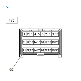
F70-21 (IG2) - Body ground |
Ignition switch ON |
11 to 14 V |
| NG | |
REPAIR OR REPLACE HARNESS OR CONNECTOR (POWER SOURCE CIRCUIT) |
|
|
4. |
CHECK HARNESS AND CONNECTOR (POWER SOURCE TERMINAL) |
|
(a) Turn the ignition switch off. |
|
(b) Measure the resistance according to the value(s) in the table below.
Standard Resistance:
|
Tester Connection |
Condition |
Specified Condition |
|---|---|---|
|
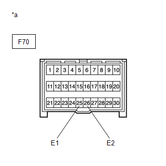
F70-25 (E1) - Body ground |
Always |
Below 1 Ω |
|
F70-26 (E2) - Body ground |
Always |
Below 1 Ω |
HINT:
If troubleshooting has been carried out according to Problem Symptoms Table, refer back to the table and proceed to the next step before replacing parts.
Click here
| OK | |
REPLACE AIRBAG SENSOR ASSEMBLY
|
| NG | |
REPAIR OR REPLACE HARNESS OR CONNECTOR (GROUND CIRCUIT) |
 SM Solenoid Circuit (C1225-C1228,C1468,C1469,C146A,C146B)
DESCRIPTION
These solenoids turn on when signals are received from the skid control ECU (brake
actuator assembly) and they control the pressure acting on the wheel cylinders to
control the brakin ...
 Speed Sensor Rotor Faulty (C1237)
DESCRIPTION
The skid control ECU (brake actuator assembly) measures the speed of each wheel
by receiving signals from each speed sensor.
These signals are used for recognizing that all four wheels ...
Other materials:
Toyota CH-R Service Manual > Front Seat Inner Belt Assembly: Components
COMPONENTS
ILLUSTRATION
*A
for Driver Side
*B
for Front Passenger Side
*1
FRONT SEAT INNER BELT ASSEMBLY
*2
FRONT SEAT BELT ANCHOR PLATE
Tightening torque for "Major areas ...
Toyota CH-R Service Manual > Revolution Sensor: Installation
INSTALLATION
PROCEDURE
1. INSTALL TRANSMISSION REVOLUTION SENSOR (NT)
(a) Apply Toyota Genuine CVT fluid FE to a new O-ring.
(b) Install the O-ring to the transmission revolution sensor (NT).
(c) Install the transmission revolution sensor (NT) to the continuously variable
transaxle assembly w ...
Toyota C-HR (AX20) 2023-2026 Owner's Manual
Toyota CH-R Owners Manual
- For safety and security
- Instrument cluster
- Operation of each component
- Driving
- Interior features
- Maintenance and care
- When trouble arises
- Vehicle specifications
- For owners
Toyota CH-R Service Manual
- Introduction
- Maintenance
- Audio / Video
- Cellular Communication
- Navigation / Multi Info Display
- Park Assist / Monitoring
- Brake (front)
- Brake (rear)
- Brake Control / Dynamic Control Systems
- Brake System (other)
- Parking Brake
- Axle And Differential
- Drive Shaft / Propeller Shaft
- K114 Cvt
- 3zr-fae Battery / Charging
- Networking
- Power Distribution
- Power Assist Systems
- Steering Column
- Steering Gear / Linkage
- Alignment / Handling Diagnosis
- Front Suspension
- Rear Suspension
- Tire / Wheel
- Tire Pressure Monitoring
- Door / Hatch
- Exterior Panels / Trim
- Horn
- Lighting (ext)
- Mirror (ext)
- Window / Glass
- Wiper / Washer
- Door Lock
- Heating / Air Conditioning
- Interior Panels / Trim
- Lighting (int)
- Meter / Gauge / Display
- Mirror (int)
- Power Outlets (int)
- Pre-collision
- Seat
- Seat Belt
- Supplemental Restraint Systems
- Theft Deterrent / Keyless Entry

0.0091