Toyota CH-R Service Manual: Back Camera Disconnected (C1622)
DESCRIPTION
This DTC is stored if the radio and display receiver assembly judges that the signals or signal lines between the radio and display receiver assembly and the rear television camera assembly are not normal as a result of its self check.
|
DTC No. |
Detection Item |
DTC Detection Condition |
Trouble Area |
|---|---|---|---|
|
C1622 |
Back Camera Disconnected |
Open or short in the rear television camera assembly signal circuit |
|
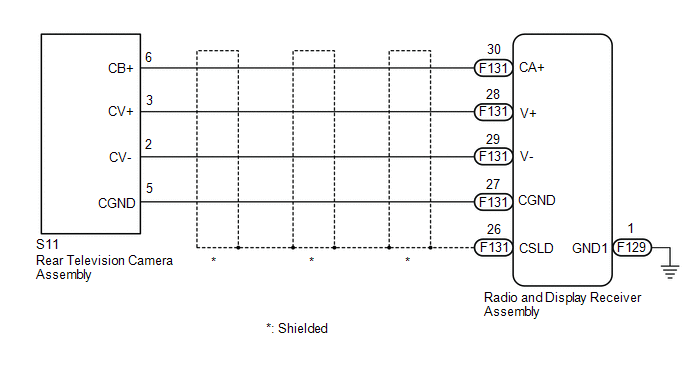
WIRING DIAGRAM
CAUTION / NOTICE / HINT
NOTICE:
- When replacing the radio and display receiver assembly, always replace
it with a new one. If a radio and display receiver assembly which was installed
to another vehicle is used, the following may occur:
- A communication malfunction DTC is stored.
- The radio and display receiver assembly may not operate normally.
PROCEDURE
|
1. |
CHECK HARNESS AND CONNECTOR (RADIO AND DISPLAY RECEIVER ASSEMBLY - REAR TELEVISION CAMERA ASSEMBLY) |
(a) Disconnect the F131 radio and display receiver assembly connector.
(b) Disconnect the S11 rear television camera assembly connector.
(c) Measure the resistance according to the value(s) in the table below.
Standard Resistance:
|
Tester Connection |
Condition |
Specified Condition |
|---|---|---|
|
F131-30 (CA+) - S11-6 (CB+) |
Always |
Below 1 Ω |
|
F131-28 (V+) - S11-3 (CV+) |
Always |
Below 1 Ω |
|
F131-29 (V-) - S11-2 (CV-) |
Always |
Below 1 Ω |
|
F131-27 (CGND) - S11-5 (CGND) |
Always |
Below 1 Ω |
|
F131-26 (CSLD) - Body ground |
Always |
Below 1 Ω |
|
F131-30 (CA+) or S11-6 (CB+) - Body ground |
Always |
10 kΩ or higher |
|
F131-28 (V+) or S11-3 (CV+) - Body ground |
Always |
10 kΩ or higher |
|
F131-29 (V-) or S11-2 (CV-) - Body ground |
Always |
10 kΩ or higher |
|
F131-27 (CGND) or S11-5 (CGND) - Body ground |
Always |
10 kΩ or higher |
| NG | .gif) |
REPAIR OR REPLACE HARNESS OR CONNECTOR |
|
.gif)
|
2. |
INSPECT RADIO AND DISPLAY RECEIVER ASSEMBLY |
(a) Reconnect the radio and display receiver assembly connector.
|
(b) Measure the resistance according to the value(s) in the table below. Standard Resistance:
|
|
(c) Measure the voltage according to the value(s) in the table below.
Standard Voltage:
|
Tester Connection |
Switch Condition |
Specified Condition |
|---|---|---|
|
F131-30 (CA+) - F131-27 (CGND) |
Ignition switch ACC |
5.5 to 7.05 V |
| NG | |
REPLACE RADIO AND DISPLAY RECEIVER ASSEMBLY |
|
|
3. |
INSPECT REAR TELEVISION CAMERA ASSEMBLY |
(a) Reconnect the S11 rear television camera assembly connector.
(b) Using an oscilloscope, check the waveform of the rear television camera assembly.
HINT:
A waterproof connector is used for the rear television camera assembly. Therefore, inspect the waveform at the radio and display receiver assembly with the connector connected.
OK:
Waveform is similar to that shown in the illustration.
|
Item |
Content |
|---|---|
|
Measurement terminal |
F131-28 (V+) - F129-1 (GND1) |
|
Measurement setting |
200 mV/DIV., 50 μs./DIV. |
|
Condition |
Ignition switch ON, shift lever in R |
HINT:
- The video waveform changes according to the image sent by the rear television camera assembly.
- The video waveform is constantly output when the ignition switch is turned to ACC.
|
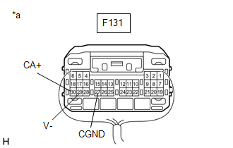
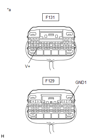
*a |
Component with harness connected (Radio and Display Receiver Assembly) |
.png)
|
*a |
Waveform 1 (camera lens is not covered, displaying an image) |
|
*b |
Waveform 2 (camera lens is covered, blacking out the screen) |
|
*c |
Synchronization Signal |
|
*d |
Video Waveform |
| OK | |
REPLACE RADIO AND DISPLAY RECEIVER ASSEMBLY |
| NG | |
REPLACE REAR TELEVISION CAMERA ASSEMBLY |
 Diagnostic Trouble Code Chart
DIAGNOSTIC TROUBLE CODE CHART
Rear View Monitor System
DTC No.
Detection Item
Link
C1622
Back Camera Disconnected
...
 Image from Camera for Rear View Monitor is Abnormal
DESCRIPTION
The video signal of the rear television camera assembly is transmitted to the
radio and display receiver assembly.
WIRING DIAGRAM
CAUTION / NOTICE / HINT
NOTICE:
When repl ...
Other materials:
Toyota CH-R Owners Manual > Do-it-yourself maintenance: Tires
Replace or rotate tires in accordance with maintenance schedules
and treadwear.
Checking tires
Check if the treadwear indicators are showing on the tires. Also check the tires
for uneven wear, such as excessive wear on one side of the tread.
Check the spare tire condition and pressure if not ...
Toyota CH-R Service Manual > Vacuum Pump: Removal
REMOVAL
CAUTION / NOTICE / HINT
The necessary procedures (adjustment, calibration, initialization, or registration)
that must be performed after parts are removed, installed, or replaced during vacuum
pump assembly removal/installation are shown below.
Necessary Procedure After Parts Removed/ ...
Toyota C-HR (AX20) 2023-2026 Owner's Manual
Toyota CH-R Owners Manual
- For safety and security
- Instrument cluster
- Operation of each component
- Driving
- Interior features
- Maintenance and care
- When trouble arises
- Vehicle specifications
- For owners
Toyota CH-R Service Manual
- Introduction
- Maintenance
- Audio / Video
- Cellular Communication
- Navigation / Multi Info Display
- Park Assist / Monitoring
- Brake (front)
- Brake (rear)
- Brake Control / Dynamic Control Systems
- Brake System (other)
- Parking Brake
- Axle And Differential
- Drive Shaft / Propeller Shaft
- K114 Cvt
- 3zr-fae Battery / Charging
- Networking
- Power Distribution
- Power Assist Systems
- Steering Column
- Steering Gear / Linkage
- Alignment / Handling Diagnosis
- Front Suspension
- Rear Suspension
- Tire / Wheel
- Tire Pressure Monitoring
- Door / Hatch
- Exterior Panels / Trim
- Horn
- Lighting (ext)
- Mirror (ext)
- Window / Glass
- Wiper / Washer
- Door Lock
- Heating / Air Conditioning
- Interior Panels / Trim
- Lighting (int)
- Meter / Gauge / Display
- Mirror (int)
- Power Outlets (int)
- Pre-collision
- Seat
- Seat Belt
- Supplemental Restraint Systems
- Theft Deterrent / Keyless Entry

0.0085