Toyota CH-R Service Manual: System Diagram
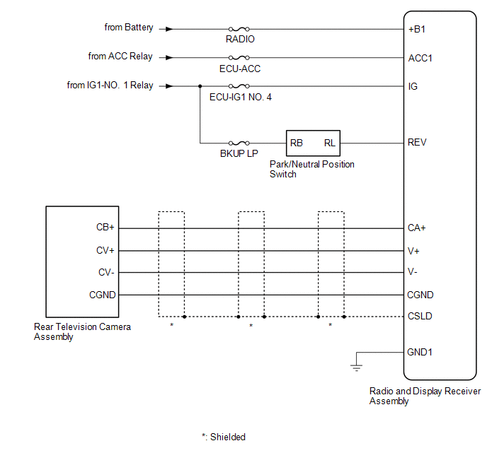
SYSTEM DIAGRAM
 Precaution
PRECAUTION
IGNITION SWITCH EXPRESSIONS
(a) The type of ignition switch used on this model differs depending on the specifications
of the vehicle. The expressions listed in the table below are used ...
 System Description
SYSTEM DESCRIPTION
GENERAL
(a) This system has a rear television camera assembly mounted on the back door
to assist the driver in parking the vehicle by displaying an image of the area behind
th ...
Other materials:
Toyota CH-R Owners Manual > Using the driving support systems: Toyota Safety Sense P
The Toyota Safety Sense P consists of the following drive assist
systems and contributes to a safe and comfortable driving experience:
PCS (Pre-Collision System)
LDA (Lane Departure Alert with steering control)
Automatic High Beam
Dynamic radar cruise control with full-speed range
WARNING� ...
Toyota CH-R Owners Manual > Using the driving support systems: Driving mode select
In response to driving conditions, one of 3 drive modes can be selected.
Select the drive mode
■ Changing the driving mode To select the drive mode, perform
operations on the multi-information display.
1. Press
or
of meter control switches and select
.
2. Press
or
of the met ...
Toyota C-HR (AX20) 2023-2026 Owner's Manual
Toyota CH-R Owners Manual
- For safety and security
- Instrument cluster
- Operation of each component
- Driving
- Interior features
- Maintenance and care
- When trouble arises
- Vehicle specifications
- For owners
Toyota CH-R Service Manual
- Introduction
- Maintenance
- Audio / Video
- Cellular Communication
- Navigation / Multi Info Display
- Park Assist / Monitoring
- Brake (front)
- Brake (rear)
- Brake Control / Dynamic Control Systems
- Brake System (other)
- Parking Brake
- Axle And Differential
- Drive Shaft / Propeller Shaft
- K114 Cvt
- 3zr-fae Battery / Charging
- Networking
- Power Distribution
- Power Assist Systems
- Steering Column
- Steering Gear / Linkage
- Alignment / Handling Diagnosis
- Front Suspension
- Rear Suspension
- Tire / Wheel
- Tire Pressure Monitoring
- Door / Hatch
- Exterior Panels / Trim
- Horn
- Lighting (ext)
- Mirror (ext)
- Window / Glass
- Wiper / Washer
- Door Lock
- Heating / Air Conditioning
- Interior Panels / Trim
- Lighting (int)
- Meter / Gauge / Display
- Mirror (int)
- Power Outlets (int)
- Pre-collision
- Seat
- Seat Belt
- Supplemental Restraint Systems
- Theft Deterrent / Keyless Entry

0.0081