Toyota CH-R Service Manual: Washer Fluid Level Warning Switch Circuit
DESCRIPTION
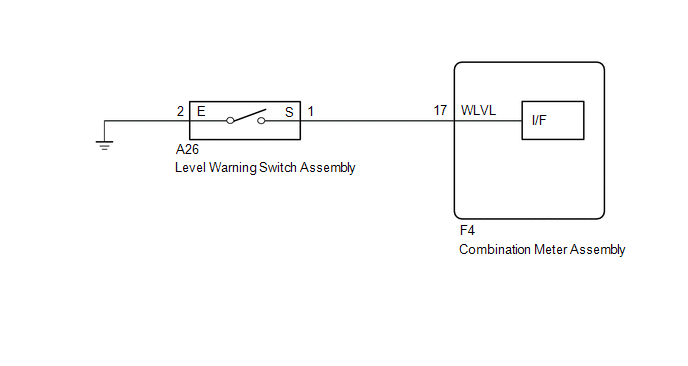
The combination meter assembly and level warning switch assembly are connected via direct line. The combination meter assembly determines the washer fluid level and outputs warning messages according to the washer fluid level warning switch ON/OFF signal.
WIRING DIAGRAM
CAUTION / NOTICE / HINT
NOTICE:
When replacing the combination meter assembly, always replace it with a new one. If a combination meter assembly which was installed to another vehicle is used, the information stored in it will not match the information from the vehicle and a DTC may be stored.
PROCEDURE
|
1. |
INSPECT LEVEL WARNING SWITCH ASSEMBLY |
(a) Remove the level warning switch assembly.
Click here .gif)
(b) Inspect the level warning switch assembly.
Click here
| NG | .gif) |
REPLACE LEVEL WARNING SWITCH ASSEMBLY |
|
.gif)
|
2. |
CHECK HARNESS AND CONNECTOR (LEVEL WARNING SWITCH ASSEMBLY - COMBINATION METER ASSEMBLY AND BODY GROUND) |
(a) Disconnect the F4 combination meter assembly connector.
(b) Measure the resistance according to the value(s) in the table below.
Standard Resistance:
|
Tester Connection |
Condition |
Specified Condition |
|---|---|---|
|
A26-1 (S) - F4-17 (WLVL) |
Always |
Below 1 Ω |
|
A26-1 (S) or F4-17 (WLVL) - Body ground |
Always |
10 kΩ or higher |
|
A26-2 (E) - Body ground |
Always |
Below 1 Ω |
| OK | |
REPLACE COMBINATION METER ASSEMBLY |
| NG | |
REPAIR OR REPLACE HARNESS OR CONNECTOR |
 Steering Pad Switch Circuit
DESCRIPTION
The combination meter assembly and steering pad switch assembly are connected
via direct line. The main display and multi-information display in the combination
meter assembly are ope ...
 Speed Signal Circuit
DESCRIPTION
The combination meter assembly receives the vehicle speed signal from this circuit.
The wheel speed sensors produce an output that varies according to the vehicle speed.
The wheel spe ...
Other materials:
Toyota CH-R Service Manual > Blind Spot Monitor System: Blind Spot Monitor Master Module Beam Axis Inspection Incomplete (C1ABB)
DESCRIPTION
This DTC is stored when a beam axis adjustment has not been performed for the
blind spot monitor sensor LH (Master).
HINT:
This DTC is always stored after replacing a blind spot monitor sensor. The purpose
of this DTC is to ensure that a beam axis adjustment is performed. Completi ...
Toyota CH-R Service Manual > Shift Lever: Installation
INSTALLATION
PROCEDURE
1. INSTALL FLOOR SHIFT SHIFT LEVER ASSEMBLY
(a) Temporarily install the floor shift shift lever assembly to the body with
the 4 bolts.
(b) Fully tighten the 4 bolts in the order shown in the illustration.
Torque:
12 N·m {122 kgf·cm, 9 ft·lbf}
(c) Engage the 6 cl ...
Toyota C-HR (AX20) 2023-2026 Owner's Manual
Toyota CH-R Owners Manual
- For safety and security
- Instrument cluster
- Operation of each component
- Driving
- Interior features
- Maintenance and care
- When trouble arises
- Vehicle specifications
- For owners
Toyota CH-R Service Manual
- Introduction
- Maintenance
- Audio / Video
- Cellular Communication
- Navigation / Multi Info Display
- Park Assist / Monitoring
- Brake (front)
- Brake (rear)
- Brake Control / Dynamic Control Systems
- Brake System (other)
- Parking Brake
- Axle And Differential
- Drive Shaft / Propeller Shaft
- K114 Cvt
- 3zr-fae Battery / Charging
- Networking
- Power Distribution
- Power Assist Systems
- Steering Column
- Steering Gear / Linkage
- Alignment / Handling Diagnosis
- Front Suspension
- Rear Suspension
- Tire / Wheel
- Tire Pressure Monitoring
- Door / Hatch
- Exterior Panels / Trim
- Horn
- Lighting (ext)
- Mirror (ext)
- Window / Glass
- Wiper / Washer
- Door Lock
- Heating / Air Conditioning
- Interior Panels / Trim
- Lighting (int)
- Meter / Gauge / Display
- Mirror (int)
- Power Outlets (int)
- Pre-collision
- Seat
- Seat Belt
- Supplemental Restraint Systems
- Theft Deterrent / Keyless Entry

0.0086