Toyota CH-R Service Manual: Manual Cut off Switch Trouble (B1651/33)
DESCRIPTION
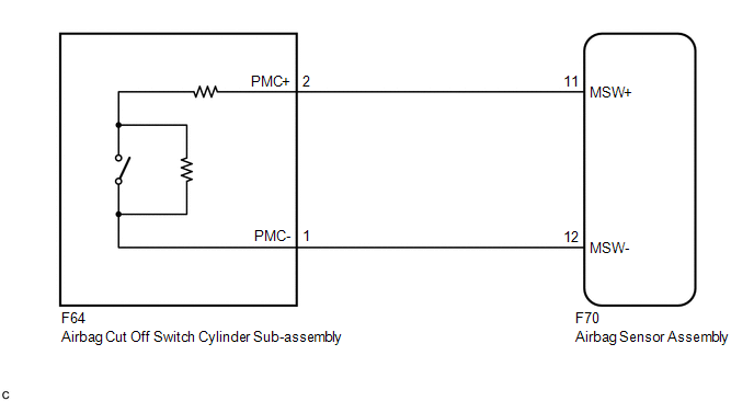
The airbag cut off switch circuit consists of the airbag sensor assembly and airbag cut off switch cylinder sub-assembly.
The instrument panel passenger without door airbag assembly can be optionally deactivated via this circuit by turning the airbag cut off switch cylinder sub-assembly to the OFF position.
If the instrument panel passenger without door airbag assembly is deactivated, the passenger airbag ON/OFF indicator ("OFF") comes on to inform the driver.
DTC B1651/33 is stored when a malfunction is detected in the airbag cut off switch circuit.
|
DTC No. |
Detection Item |
DTC Detection Condition |
Trouble Area |
Test Mode / Check Mode |
|---|---|---|---|---|
|
B1651/33 |
Manual Cut off Switch Trouble |
Any of the following conditions is met:
|
|
Does not apply to test/check mode |
|
Vehicle Condition |
|||||||
|---|---|---|---|---|---|---|---|
|
Pattern 1 |
Pattern 2 |
Pattern 3 |
Pattern 4 |
Pattern 5 |
Pattern 6 |
||
|
Diagnosis Condition |
Ignition switch ON |
○ |
○ |
○ |
○ |
○ |
○ |
|
Malfunction Status |
The airbag sensor assembly detects a line short, in the airbag cut off switch circuit |
○ |
- |
- |
- |
- |
- |
|
The airbag sensor assembly detects a short to ground in the airbag cut off switch circuit |
- |
○ |
- |
- |
- |
- |
|
|
The airbag sensor assembly detects a short to B+ in the airbag cut off switch circuit |
- |
- |
○ |
- |
- |
- |
|
|
The airbag sensor assembly detects an open in the airbag cut off switch circuit |
- |
- |
- |
○ |
- |
- |
|
|
Airbag cut off switch cylinder sub-assembly malfunction |
- |
- |
- |
- |
○ |
- |
|
|
Airbag sensor assembly malfunction |
- |
- |
- |
- |
- |
○ |
|
|
Detection Time |
- |
- |
- |
- |
- |
- |
|
|
Number of Trips |
1 trip |
1 trip |
1 trip |
1 trip |
1 trip |
1 trip |
|
HINT:
DTC will be output when conditions for either of the patterns in the table above are met.
WIRING DIAGRAM
CAUTION / NOTICE / HINT
NOTICE:
After turning the ignition switch off, waiting time may be required before disconnecting the cable from the negative (-) battery terminal. Therefore, make sure to read the disconnecting the cable from the negative (-) battery terminal notices before proceeding with work.
Click here .gif)
HINT:
Terminals F70-11 (MSW+) and F70-12 (MSW-) of the instrument panel wire in this circuit have an activation prevention mechanism.
This mechanism can be used to check for an open circuit in the wire harness. When performing other checks (check for short, short to ground or short to B+), this mechanism should be released.
PROCEDURE
|
1. |
CHECK CONNECTORS |
(a) Turn the ignition switch off.
(b) Disconnect the cable from the negative (-) battery terminal.
CAUTION:
Wait at least 90 seconds after disconnecting the cable from the negative (-) battery terminal to disable the SRS system.
(c) Check that the connectors are properly connected to the airbag sensor assembly and airbag cut off switch cylinder sub-assembly.
OK:
The connectors are properly connected.
HINT:
If the connectors are not properly connected, reconnect the connectors and proceed to the next inspection.
(d) Disconnect the connectors from the airbag sensor assembly and airbag cut off switch cylinder sub-assembly.
(e) Check that the terminals of the connectors are not deformed or damaged.
OK:
The terminals are not deformed or damaged.
(f) Check that the short springs of the activation prevention mechanism of the instrument panel wire connector are not deformed or damaged.
OK:
The short springs are not deformed or damaged.
| NG | .gif) |
REPLACE INSTRUMENT PANEL WIRE |
|
.gif)
|
2. |
CHECK INSTRUMENT PANEL WIRE (OPEN) |
|
(a) Measure the resistance according to the value(s) in the table below. Standard Resistance:
|
|
| NG | |
REPLACE INSTRUMENT PANEL WIRE |
|
|
3. |
CHECK INSTRUMENT PANEL WIRE (SHORT) |
|
(a) Release the activation prevention mechanism built into connector B. Click here |
|
(b) Measure the resistance according to the value(s) in the table below.
Standard Resistance:
|
Tester Connection |
Condition |
Specified Condition |
|---|---|---|
|
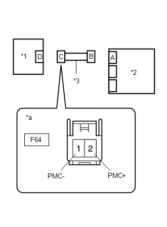
F64-2 (PMC+) - F64-1 (PMC-) |
Always |
1 MΩ or higher |
| NG | |
REPLACE INSTRUMENT PANEL WIRE |
|
|
4. |
CHECK INSTRUMENT PANEL WIRE (SHORT TO B+) |
|
(a) Connect the cable to the negative (-) battery terminal. |
|
(b) Turn the ignition switch ON.
(c) Measure the voltage according to the value(s) in the table below.
Standard Voltage:
|
Tester Connection |
Switch Condition |
Specified Condition |
|---|---|---|
|
F64-2 (PMC+) - Body ground |
Ignition switch ON |
Below 1 V |
|
F64-1 (PMC-) - Body ground |
Ignition switch ON |
Below 1 V |
(d) Turn the ignition switch off.
(e) Disconnect the cable from the negative (-) battery terminal.
CAUTION:
Wait at least 90 seconds after disconnecting the cable from the negative (-) battery terminal to disable the SRS system.
| NG | |
REPLACE INSTRUMENT PANEL WIRE |
|
|
5. |
CHECK INSTRUMENT PANEL WIRE (SHORT TO GROUND) |
|
(a) Measure the resistance according to the value(s) in the table below. Standard Resistance:
|
|
(b) Restore the released activation prevention mechanism of connector B to the original condition.
| NG | |
REPLACE INSTRUMENT PANEL WIRE |
|
|
6. |
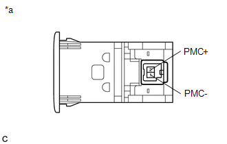
CHECK AIRBAG CUT OFF SWITCH CYLINDER SUB-ASSEMBLY |
|
(a) Measure the resistance according to the value(s) in the table below. Standard Resistance:
|
|
| NG | |
REPLACE AIRBAG CUT OFF SWITCH CYLINDER SUB-ASSEMBLY |
|
|
7. |
CHECK DTC |
|
(a) Connect the connectors to the airbag sensor assembly and airbag cut off switch cylinder sub-assembly. |
|
.png)
(b) Connect the cable to the negative (-) battery terminal.
(c) Clear the DTCs stored in memory.
Click here
(d) Turn the ignition switch off.
(e) Turn the ignition switch ON, and wait for at least 60 seconds.
(f) Check for DTCs.
Click here
OK:
DTC B1651/33 is not output.
HINT:
Codes other than DTC B1651/33 may be output at this time, but they are not related to this check.
| OK | |
USE SIMULATION METHOD TO CHECK |
| NG | |
REPLACE AIRBAG SENSOR ASSEMBLY |
 Occupant Classification System Malfunction (B1650/32,B165A/32)
DESCRIPTION
The airbag sensor assembly and occupant detection ECU communicate via CAN communication.
When the occupant detection ECU stores DTC B1771, B1780, B1782, B1795, B1798,
B1799, U0125 or U ...
 Passenger Airbag ON/OFF Indicator Circuit Malfunction (B1660/43)
DESCRIPTION
The passenger airbag ON/OFF indicator circuit consists of the airbag sensor assembly
and passenger airbag ON/OFF indicator.
The passenger airbag ON/OFF indicator indicates the operatio ...
Other materials:
Toyota CH-R Owners Manual > BSM (Blind Spot Monitor): RCTA function
The RCTA functions when your vehicle is in reverse. It can detect other vehicles
approaching from the right or left rear of the vehicle. It uses radar sensors to
alert the driver of the other vehicle's existence through flashing the outside rear
view mirror indicators and sounding a buzzer ...
Toyota CH-R Service Manual > K114 Continuously Variable Transaxle Fluid: Components
COMPONENTS
ILLUSTRATION
*1
REFILL PLUG
*2
OVERFLOW PLUG
*3
NO. 1 TRANSMISSION OIL FILLER TUBE
*4
DRAIN PLUG
*5
NO. 1 ENGINE UNDER COVER
*6
REAR ENGINE U ...
Toyota C-HR (AX20) 2023-2026 Owner's Manual
Toyota CH-R Owners Manual
- For safety and security
- Instrument cluster
- Operation of each component
- Driving
- Interior features
- Maintenance and care
- When trouble arises
- Vehicle specifications
- For owners
Toyota CH-R Service Manual
- Introduction
- Maintenance
- Audio / Video
- Cellular Communication
- Navigation / Multi Info Display
- Park Assist / Monitoring
- Brake (front)
- Brake (rear)
- Brake Control / Dynamic Control Systems
- Brake System (other)
- Parking Brake
- Axle And Differential
- Drive Shaft / Propeller Shaft
- K114 Cvt
- 3zr-fae Battery / Charging
- Networking
- Power Distribution
- Power Assist Systems
- Steering Column
- Steering Gear / Linkage
- Alignment / Handling Diagnosis
- Front Suspension
- Rear Suspension
- Tire / Wheel
- Tire Pressure Monitoring
- Door / Hatch
- Exterior Panels / Trim
- Horn
- Lighting (ext)
- Mirror (ext)
- Window / Glass
- Wiper / Washer
- Door Lock
- Heating / Air Conditioning
- Interior Panels / Trim
- Lighting (int)
- Meter / Gauge / Display
- Mirror (int)
- Power Outlets (int)
- Pre-collision
- Seat
- Seat Belt
- Supplemental Restraint Systems
- Theft Deterrent / Keyless Entry

0.0083