Toyota CH-R Service Manual: Passenger Airbag ON/OFF Indicator Circuit Malfunction (B1660/43)
DESCRIPTION
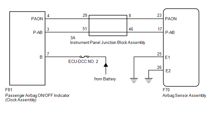
The passenger airbag ON/OFF indicator circuit consists of the airbag sensor assembly and passenger airbag ON/OFF indicator.
The passenger airbag ON/OFF indicator indicates the operation condition of the instrument panel passenger without door airbag assembly.
DTC B1660/43 is stored when a malfunction is detected in the passenger airbag ON/OFF indicator circuit.
|
DTC No. |
Detection Item |
DTC Detection Condition |
Trouble Area |
Test Mode / Check Mode |
|---|---|---|---|---|
|
B1660/43 |
Passenger Airbag ON/OFF Indicator Circuit Malfunction |
Any of the following conditions is met:
|
|
Does not apply to test/check mode |
|
Vehicle Condition |
|||||||
|---|---|---|---|---|---|---|---|
|
Pattern 1 |
Pattern 2 |
Pattern 3 |
Pattern 4 |
Pattern 5 |
Pattern 6 |
||
|
Diagnosis Condition |
Ignition switch ON |
○ |
○ |
○ |
○ |
○ |
○ |
|
Malfunction Status |
The airbag sensor assembly detects a line short in the passenger airbag ON/OFF indicator circuit |
○ |
- |
- |
- |
- |
- |
|
The airbag sensor assembly detects a short to ground in the passenger airbag ON/OFF indicator circuit |
- |
○ |
- |
- |
- |
- |
|
|
The airbag sensor assembly detects a short to B+ in the passenger airbag ON/OFF indicator circuit |
- |
- |
○ |
- |
- |
- |
|
|
The airbag sensor assembly detects an open in the passenger airbag ON/OFF indicator circuit |
- |
- |
- |
○ |
- |
- |
|
|
Passenger airbag ON/OFF indicator malfunction |
- |
- |
- |
- |
○ |
- |
|
|
Airbag sensor assembly malfunction |
- |
- |
- |
- |
- |
○ |
|
|
Detection Time |
- |
- |
- |
- |
- |
- |
|
|
Number of Trips |
1 trip |
1 trip |
1 trip |
1 trip |
1 trip |
1 trip |
|
HINT:
DTC will be output when conditions for either of the patterns in the table above are met.
WIRING DIAGRAM
CAUTION / NOTICE / HINT
NOTICE:
- After turning the ignition switch off, waiting time may be required
before disconnecting the cable from the negative (-) battery terminal. Therefore,
make sure to read the disconnecting the cable from the negative (-) battery
terminal notices before proceeding with work.
Click here
.gif)
- Inspect the fuses for circuits related to this system before performing the following procedure.
PROCEDURE
|
1. |
CHECK PASSENGER AIRBAG ON/OFF INDICATOR CONDITION |
(a) Turn the ignition switch ON.
(b) Check the passenger airbag ON/OFF indicator operation.
HINT:
Refer to the normal condition of the passenger airbag ON/OFF indicator.
Click here
|
Result |
Proceed to |
|---|---|
|
Passenger airbag ON/OFF indicator illumination is always on. |
A |
|
Passenger airbag ON/OFF indicator illumination is always off. |
B |
| B | .gif) |
GO TO STEP 13 |
|
.gif)
|
2. |
CHECK CONNECTORS |
(a) Turn the ignition switch ON.
(b) Disconnect the cable from the negative (-) battery terminal.
CAUTION:
Wait at least 90 seconds after disconnecting the cable from the negative (-) battery terminal to disable the SRS system.
(c) Check that the connectors are properly connected to the airbag sensor assembly, passenger airbag ON/OFF indicator (clock assembly) and instrument panel junction block assembly.
OK:
The connectors are properly connected.
HINT:
If the connectors are not properly connected, reconnect the connectors and proceed to the next inspection.
(d) Disconnect the connectors from the airbag sensor assembly, passenger airbag ON/OFF indicator (clock assembly) and instrument panel junction block assembly.
(e) Check that the terminals of the connectors are not deformed or damaged.
OK:
The terminals are not deformed or damaged.
| NG | |
REPLACE INSTRUMENT PANEL WIRE |
|
|
3. |
CHECK PASSENGER AIRBAG ON/OFF INDICATOR CONDITION |
(a) Connect the connector to the passenger airbag ON/OFF indicator (clock assembly) and instrument panel junction block assembly.
(b) Connect the cable to the negative (-) battery terminal.
(c) Turn the ignition switch ON.
(d) Check the passenger airbag ON/OFF indicator operation.
OK:
The passenger airbag ON/OFF indicator does not come on.
| NG | |
GO TO STEP 5 |
|
|
4. |
CHECK DTC |
|
(a) Turn the ignition switch off. |
|
(b) Disconnect the cable from the negative (-) battery terminal.
CAUTION:
Wait at least 90 seconds after disconnecting the cable from the negative (-) battery terminal to disable the SRS system.
(c) Connect the connector to the airbag sensor assembly.
(d) Connect the cable to the negative (-) battery terminal.
(e) Clear the DTCs stored in memory.
Click here
(f) Turn the ignition switch off.
(g) Turn the ignition switch ON, and wait for at least 60 seconds.
(h) Check for DTCs.
Click here
OK:
DTC B1660/43 is not output.
HINT:
Codes other than DTC B1660/43 may be output at this time, but they are not related to this check.
| OK | |
USE SIMULATION METHOD TO CHECK |
| NG | |
REPLACE AIRBAG SENSOR ASSEMBLY |
|
5. |
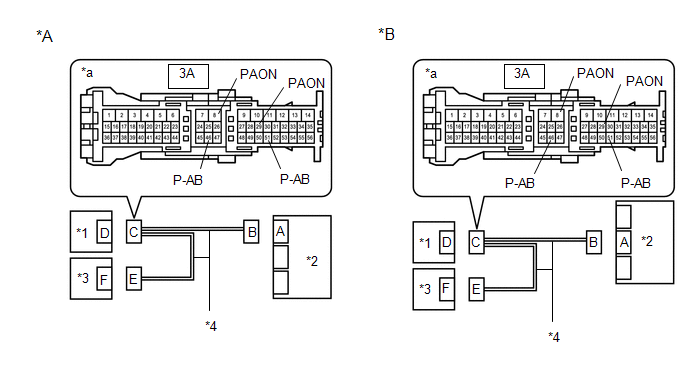
CHECK WIRE HARNESS (OPEN) |
(a) Turn the ignition switch off.
|
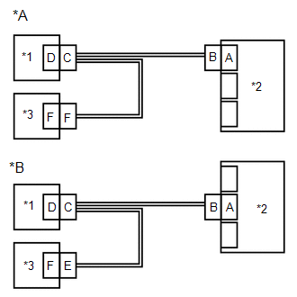
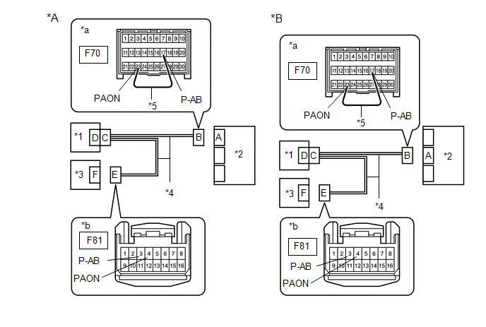
*A |
w/o Occupant Classification System |
*B |
w/ Occupant Classification System |
|
*1 |
Instrument Panel Junction Block Assembly |
*2 |
Airbag Sensor Assembly |
|
*3 |
Passenger Airbag ON/OFF Indicator (Clock Assembly) |
*4 |
Instrument Panel Wire |
|
*5 |
Service Wire |
- |
- |
|
*a |
Front view of wire harness connector (to Airbag Sensor Assembly) |
*b |
Front view of wire harness connector (to Passenger Airbag ON/OFF Indicator (Clock Assembly)) |
(b) Disconnect the cable from the negative (-) battery terminal.
CAUTION:
Wait at least 90 seconds after disconnecting the cable from the negative (-) battery terminal to disable the SRS system.
(c) Disconnect the connector from the passenger airbag ON/OFF indicator (clock assembly).
(d) Using a service wire, connect terminals 23 (PAON) and 17 (P-AB) of connector B.
NOTICE:
Do not forcibly insert the service wire into the terminals of the connector when connecting the wire.
(e) Measure the resistance according to the value(s) in the table below.
Standard Resistance:
|
Tester Connection |
Condition |
Specified Condition |
|---|---|---|
|
F81-4 (PAON) - F81-3 (P-AB) |
Always |
Below 1 Ω |
| NG | |
GO TO STEP 12 |
|
|
6. |
CHECK WIRE HARNESS (SHORT) |
(a) Disconnect the service wire from connector B.
|
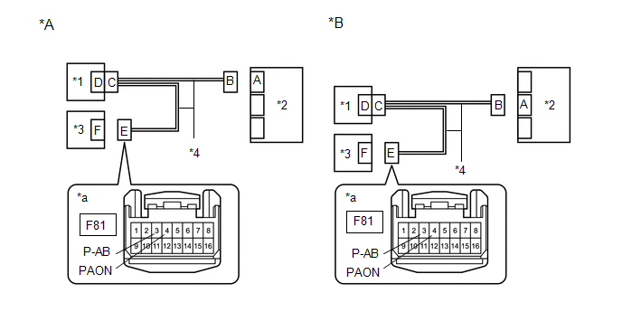
*A |
w/o Occupant Classification System |
*B |
w/ Occupant Classification System |
|
*1 |
Instrument Panel Junction Block Assembly |
*2 |
Airbag Sensor Assembly |
|
*3 |
Passenger Airbag ON/OFF Indicator (Clock Assembly) |
*4 |
Instrument Panel Wire |
|
*a |
Front view of wire harness connector (to Passenger Airbag ON/OFF Indicator (Clock Assembly)) |
- |
- |
(b) Measure the resistance according to the value(s) in the table below.
Standard Resistance:
|
Tester Connection |
Condition |
Specified Condition |
|---|---|---|
|
F81-4 (PAON) - F81-3 (P-AB) |
Always |
1 MΩ or higher |
| NG | |
GO TO STEP 11 |
|
|
7. |
CHECK WIRE HARNESS (SHORT TO B+) |
(a) Connect the cable to the negative (-) battery terminal.
|
*A |
w/o Occupant Classification System |
*B |
w/ Occupant Classification System |
|
*1 |
Instrument Panel Junction Block Assembly |
*2 |
Airbag Sensor Assembly |
|
*3 |
Passenger Airbag ON/OFF Indicator (Clock Assembly) |
*4 |
Instrument Panel Wire |
|
*a |
Front view of wire harness connector (to Passenger Airbag ON/OFF Indicator (Clock Assembly)) |
- |
- |
(b) Turn the ignition switch ON.
(c) Measure the voltage according to the value(s) in the table below.
Standard Voltage:
|
Tester Connection |
Switch Condition |
Specified Condition |
|---|---|---|
|
F81-4 (PAON) - Body ground |
Ignition switch ON |
Below 1 V |
|
F81-3 (P-AB) - Body ground |
Ignition switch ON |
Below 1 V |
(d) Turn the ignition switch off.
(e) Disconnect the cable from the negative (-) battery terminal.
CAUTION:
Wait at least 90 seconds after disconnecting the cable from the negative (-) battery terminal to disable the SRS system.
| NG | |
GO TO STEP 10 |
|
|
8. |
CHECK WIRE HARNESS (SHORT TO GROUND) |
(a) Measure the resistance according to the value(s) in the table below.
|
*A |
w/o Occupant Classification System |
*B |
w/ Occupant Classification System |
|
*1 |
Instrument Panel Junction Block Assembly |
*2 |
Airbag Sensor Assembly |
|
*3 |
Passenger Airbag ON/OFF Indicator (Clock Assembly) |
*4 |
Instrument Panel Wire |
|
*a |
Front view of wire harness connector (to Passenger Airbag ON/OFF Indicator (Clock Assembly)) |
- |
- |
Standard Resistance:
|
Tester Connection |
Condition |
Specified Condition |
|---|---|---|
|
F81-4 (PAON) - Body ground |
Always |
1 MΩ or higher |
|
F81-3 (P-AB) - Body ground |
Always |
1 MΩ or higher |
| OK | |
REPLACE PASSENGER AIRBAG ON/OFF INDICATOR (CLOCK ASSEMBLY)
|
|
|
9. |
CHECK INSTRUMENT PANEL WIRE (SHORT TO GROUND) |
(a) Disconnect the connector from the instrument panel junction block assembly.
|
*A |
w/o Occupant Classification System |
*B |
w/ Occupant Classification System |
|
*1 |
Instrument Panel Junction Block Assembly |
*2 |
Airbag Sensor Assembly |
|
*3 |
Passenger Airbag ON/OFF Indicator (Clock Assembly) |
*4 |
Instrument Panel Wire |
|
*a |
Front view of wire harness connector (to Instrument Panel Junction Block Assembly) |
- |
- |
(b) Measure the resistance according to the value(s) in the table below.
Standard Resistance:
|
Tester Connection |
Condition |
Specified Condition |
|---|---|---|
|
3A-8 (PAON) - Body ground |
Always |
1 MΩ or higher |
|
3A-29 (PAON) - Body ground |
Always |
1 MΩ or higher |
|
3A-46 (P-AB) - Body ground |
Always |
1 MΩ or higher |
|
3A-51 (P-AB) - Body ground |
Always |
1 MΩ or higher |
| OK | |
REPLACE INSTRUMENT PANEL JUNCTION BLOCK ASSEMBLY |
| NG | |
REPLACE INSTRUMENT PANEL WIRE |
|
10. |
CHECK INSTRUMENT PANEL WIRE (SHORT TO B+) |
(a) Disconnect the connector from the instrument panel junction block assembly.
|
*A |
w/o Occupant Classification System |
*B |
w/ Occupant Classification System |
|
*1 |
Instrument Panel Junction Block Assembly |
*2 |
Airbag Sensor Assembly |
|
*3 |
Passenger Airbag ON/OFF Indicator (Clock Assembly) |
*4 |
Instrument Panel Wire |
|
*a |
Front view of wire harness connector (to Instrument Panel Junction Block Assembly) |
- |
- |
(b) Connect the cable to the negative (-) battery terminal.
(c) Turn the ignition switch ON.
(d) Measure the voltage according to the value(s) in the table below.
Standard Voltage:
|
Tester Connection |
Switch Condition |
Specified Condition |
|---|---|---|
|
3A-8 (PAON) - Body ground |
Ignition switch ON |
Below 1 V |
|
3A-29 (PAON) - Body ground |
Ignition switch ON |
Below 1 V |
|
3A-46 (P-AB) - Body ground |
Ignition switch ON |
Below 1 V |
|
3A-51 (P-AB) - Body ground |
Ignition switch ON |
Below 1 V |
(e) Turn the ignition switch off.
(f) Disconnect the cable from the negative (-) battery terminal.
CAUTION:
Wait at least 90 seconds after disconnecting the cable from the negative (-) battery terminal to disable the SRS system.
| OK | |
REPLACE INSTRUMENT PANEL JUNCTION BLOCK ASSEMBLY |
| NG | |
REPLACE INSTRUMENT PANEL WIRE |
|
11. |
CHECK INSTRUMENT PANEL WIRE (SHORT) |
(a) Disconnect the connector from the instrument panel junction block assembly.
|
*A |
w/o Occupant Classification System |
*B |
w/ Occupant Classification System |
|
*1 |
Instrument Panel Junction Block Assembly |
*2 |
Airbag Sensor Assembly |
|
*3 |
Passenger Airbag ON/OFF Indicator (Clock Assembly) |
*4 |
Instrument Panel Wire |
|
*a |
Front view of wire harness connector (to Instrument Panel Junction Block Assembly) |
- |
- |
(b) Measure the resistance according to the value(s) in the table below.
Standard Resistance:
|
Tester Connection |
Condition |
Specified Condition |
|---|---|---|
|
3A-8 (PAON) - 3A-46 (P-AB) |
Always |
1 MΩ or higher |
|
3A-29 (PAON) - 3A-51 (P-AB) |
Always |
1 MΩ or higher |
| OK | |
REPLACE INSTRUMENT PANEL JUNCTION BLOCK ASSEMBLY |
| NG | |
REPLACE INSTRUMENT PANEL WIRE |
|
12. |
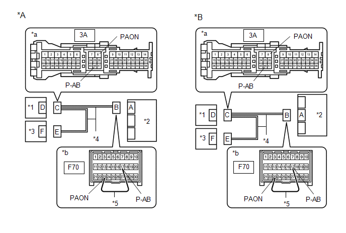
CHECK INSTRUMENT PANEL WIRE (OPEN) |
(a) Disconnect the connector from the instrument panel junction block assembly.
|
*A |
w/o Occupant Classification System |
*B |
w/ Occupant Classification System |
|
*1 |
Instrument Panel Junction Block Assembly |
*2 |
Airbag Sensor Assembly |
|
*3 |
Passenger Airbag ON/OFF Indicator (Clock Assembly) |
*4 |
Instrument Panel Wire |
|
*5 |
Service Wire |
- |
- |
|
*a |
Front view of wire harness connector (to Instrument Panel Junction Block Assembly) |
*b |
Front view of wire harness connector (to Airbag Sensor Assembly) |
HINT:
The service wire has already been inserted into connector B.
(b) Measure the resistance according to the value(s) in the table below.
Standard Resistance:
|
Tester Connection |
Condition |
Specified Condition |
|---|---|---|
|
3A-8 (PAON) - 3A-46 (P-AB) |
Always |
Below 1 Ω |
(c) Disconnect the service wire from connector B.
(d) Using a service wire, connect terminals 3 (P-AB) and 4 (PAON) of connector E.
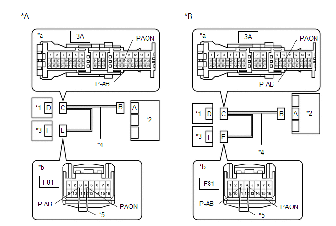
|
*A |
w/o Occupant Classification System |
*B |
w/ Occupant Classification System |
|
*1 |
Instrument Panel Junction Block Assembly |
*2 |
Airbag Sensor Assembly |
|
*3 |
Passenger Airbag ON/OFF Indicator (Clock Assembly) |
*4 |
Instrument Panel Wire |
|
*5 |
Service Wire |
- |
- |
|
*a |
Front view of wire harness connector (to Instrument Panel Junction Block Assembly) |
*b |
Front view of wire harness connector (to Passenger Airbag ON/OFF Indicator (Clock Assembly)) |
NOTICE:
Do not forcibly insert the service wire into the terminals of the connector when connecting the wire.
(e) Measure the resistance according to the value(s) in the table below.
Standard Resistance:
|
Tester Connection |
Condition |
Specified Condition |
|---|---|---|
|
3A-29 (PAON) - 3A-51 (P-AB) |
Always |
Below 1 Ω |
(f) Disconnect the service wire from connector E.
| OK | |
REPLACE INSTRUMENT PANEL JUNCTION BLOCK ASSEMBLY |
| NG | |
REPLACE INSTRUMENT PANEL WIRE |
|
13. |
CHECK CONNECTORS |
(a) Turn the ignition switch off.
(b) Disconnect the cable from the negative (-) battery terminal.
CAUTION:
Wait at least 90 seconds after disconnecting the cable from the negative (-) battery terminal to disable the SRS system.
(c) Check that the connectors are properly connected to the airbag sensor assembly, passenger airbag ON/OFF indicator (clock assembly) and instrument panel junction block assembly.
OK:
The connectors are properly connected.
HINT:
If the connectors are not properly connected, reconnect the connectors and proceed to the next inspection.
(d) Disconnect the connectors from the airbag sensor assembly, passenger airbag ON/OFF indicator (clock assembly) and instrument panel junction block assembly.
(e) Check that the terminals of the connectors are not deformed or damaged.
OK:
The terminals are not deformed or damaged.
| NG | |
REPLACE INSTRUMENT PANEL WIRE |
|
|
14. |
CHECK WIRE HARNESS (OPEN) |
(a) Connect the connector to the instrument panel junction block assembly.
|
*A |
w/o Occupant Classification System |
*B |
w/ Occupant Classification System |
|
*1 |
Instrument Panel Junction Block Assembly |
*2 |
Airbag Sensor Assembly |
|
*3 |
Passenger Airbag ON/OFF Indicator (Clock Assembly) |
*4 |
Instrument Panel Wire |
|
*5 |
Service Wire |
- |
- |
|
*a |
Front view of wire harness connector (to Airbag Sensor Assembly) |
*b |
Front view of wire harness connector (to Passenger Airbag ON/OFF Indicator (Clock Assembly)) |
(b) Using a service wire, connect terminals 23 (PAON) and 17 (P-AB) of connector B.
NOTICE:
Do not forcibly insert the service wire into the terminals of the connector when connecting the wire.
(c) Measure the resistance according to the value(s) in the table below.
Standard Resistance:
|
Tester Connection |
Condition |
Specified Condition |
|---|---|---|
|
F81-4 (PAON) - F81-3 (P-AB) |
Always |
Below 1 Ω |
| NG | |
GO TO STEP 24 |
|
|
15. |
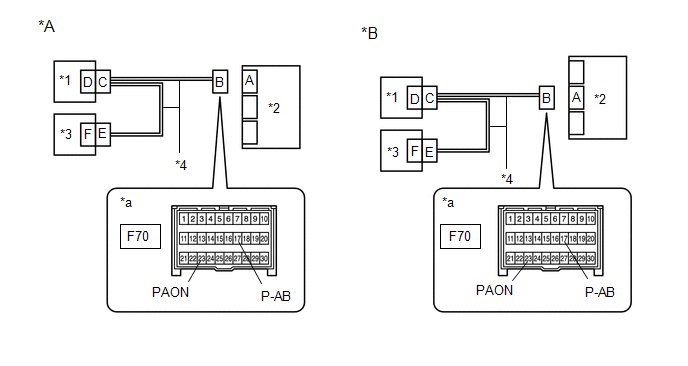
CHECK WIRE HARNESS (SHORT) |
(a) Disconnect the service wire from connector B.
|
*A |
w/o Occupant Classification System |
*B |
w/ Occupant Classification System |
|
*1 |
Instrument Panel Junction Block Assembly |
*2 |
Airbag Sensor Assembly |
|
*3 |
Passenger Airbag ON/OFF Indicator (Clock Assembly) |
*4 |
Instrument Panel Wire |
|
*a |
Front view of wire harness connector (to Passenger Airbag ON/OFF Indicator (Clock Assembly)) |
- |
- |
(b) Measure the resistance according to the value(s) in the table below.
Standard Resistance:
|
Tester Connection |
Condition |
Specified Condition |
|---|---|---|
|
F81-4 (PAON) - F81-3 (P-AB) |
Always |
1 MΩ or higher |
| NG | |
GO TO STEP 23 |
|
|
16. |
CHECK WIRE HARNESS (SHORT TO B+) |
(a) Connect the cable to the negative (-) battery terminal.
|
*A |
w/o Occupant Classification System |
*B |
w/ Occupant Classification System |
|
*1 |
Instrument Panel Junction Block Assembly |
*2 |
Airbag Sensor Assembly |
|
*3 |
Passenger Airbag ON/OFF Indicator (Clock Assembly) |
*4 |
Instrument Panel Wire |
|
*a |
Front view of wire harness connector (to Passenger Airbag ON/OFF Indicator (Clock Assembly)) |
- |
- |
(b) Turn the ignition switch ON.
(c) Measure the voltage according to the value(s) in the table below.
Standard Voltage:
|
Tester Connection |
Switch Condition |
Specified Condition |
|---|---|---|
|
F81-4 (PAON) - Body ground |
Ignition switch ON |
Below 1 V |
|
F81-3 (P-AB) - Body ground |
Ignition switch ON |
Below 1 V |
(d) Turn the ignition switch off.
(e) Disconnect the cable from the negative (-) battery terminal.
CAUTION:
Wait at least 90 seconds after disconnecting the cable from the negative (-) battery terminal to disable the SRS system.
| NG | |
GO TO STEP 22 |
|
|
17. |
CHECK WIRE HARNESS (SHORT TO GROUND) |
(a) Measure the resistance according to the value(s) in the table below.
|
*A |
w/o Occupant Classification System |
*B |
w/ Occupant Classification System |
|
*1 |
Instrument Panel Junction Block Assembly |
*2 |
Airbag Sensor Assembly |
|
*3 |
Passenger Airbag ON/OFF Indicator (Clock Assembly) |
*4 |
Instrument Panel Wire |
|
*a |
Front view of wire harness connector (to Passenger Airbag ON/OFF Indicator (Clock Assembly)) |
- |
- |
Standard Resistance:
|
Tester Connection |
Condition |
Specified Condition |
|---|---|---|
|
F81-4 (PAON) - Body ground |
Always |
1 MΩ or higher |
|
F81-3 (P-AB) - Body ground |
Always |
1 MΩ or higher |
| NG | |
GO TO STEP 21 |
|
|
18. |
CHECK PASSENGER AIRBAG ON/OFF INDICATOR (SOURCE VOLTAGE) |
(a) Connect the cable to the negative (-) battery terminal.
|
*A |
w/o Occupant Classification System |
*B |
w/ Occupant Classification System |
|
*1 |
Instrument Panel Junction Block Assembly |
*2 |
Airbag Sensor Assembly |
|
*3 |
Passenger Airbag ON/OFF Indicator (Clock Assembly) |
*4 |
Instrument Panel Wire |
|
*a |
Front view of wire harness connector (to Passenger Airbag ON/OFF Indicator (Clock Assembly)) |
- |
- |
(b) Measure the voltage according to the value(s) in the table below.
Standard Voltage:
|
Tester Connection |
Switch Condition |
Specified Condition |
|---|---|---|
|
F81-7 (B) - Body ground |
Ignition switch off |
11 to 14 V |
(c) Disconnect the cable from the negative (-) battery terminal.
CAUTION:
Wait at least 90 seconds after disconnecting the cable from the negative (-) battery terminal to disable the SRS system.
| NG | |
REPLACE WIRE HARNESS OR BATTERY |
|
|
19. |
CHECK PASSENGER AIRBAG ON/OFF INDICATOR |
(a) Connect the connector to the passenger airbag ON/OFF indicator (clock assembly).
|
*A |
w/o Occupant Classification System |
*B |
w/ Occupant Classification System |
|
*1 |
Instrument Panel Junction Block Assembly |
*2 |
Airbag Sensor Assembly |
|
*3 |
Passenger Airbag ON/OFF Indicator (Clock Assembly) |
*4 |
Instrument Panel Wire |
|
*a |
Front view of wire harness connector (to Airbag Sensor Assembly) |
- |
- |
(b) Connect the cable to the negative (-) battery terminal.
(c) Turn the ignition switch ON.
(d) Check the passenger airbag ON/OFF indicator according to the conditions in the table below.
OK:
|
Terminal Connection |
Switch Condition |
Specified Condition |
|---|---|---|
|
F70-23 (PAON) - Body ground |
Ignition switch ON |
"ON" comes on |
|
F70-17 (P-AB) - Body ground |
Ignition switch ON |
"OFF" comes on |
(e) Turn the ignition switch off.
(f) Disconnect the cable from the negative (-) battery terminal.
CAUTION:
Wait at least 90 seconds after disconnecting the cable from the negative (-) battery terminal to disable the SRS system.
| NG | |
REPLACE PASSENGER AIRBAG ON/OFF INDICATOR (CLOCK ASSEMBLY)
|
|
|
20. |
CHECK DTC |
|
(a) Connect the connector to the airbag sensor assembly. |
|
(b) Connect the cable to the negative (-) battery terminal.
(c) Clear the DTCs stored in memory.
Click here
(d) Turn the ignition switch off.
(e) Turn the ignition switch ON, and wait for at least 60 seconds.
(f) Check for DTCs.
Click here
OK:
DTC B1660/43 is not output.
HINT:
Codes other than DTC B1660/43 may be output at this time, but they are not related to this check.
| OK | |
USE SIMULATION METHOD TO CHECK |
| NG | |
REPLACE AIRBAG SENSOR ASSEMBLY |
|
21. |
CHECK INSTRUMENT PANEL WIRE (SHORT TO GROUND) |
(a) Disconnect the connector from the instrument panel junction block assembly.
|
*A |
w/o Occupant Classification System |
*B |
w/ Occupant Classification System |
|
*1 |
Instrument Panel Junction Block Assembly |
*2 |
Airbag Sensor Assembly |
|
*3 |
Passenger Airbag ON/OFF Indicator (Clock Assembly) |
*4 |
Instrument Panel Wire |
|
*a |
Front view of wire harness connector (to Instrument Panel Junction Block Assembly) |
- |
- |
(b) Measure the resistance according to the value(s) in the table below.
Standard Resistance:
|
Tester Connection |
Condition |
Specified Condition |
|---|---|---|
|
3A-8 (PAON) - Body ground |
Always |
1 MΩ or higher |
|
3A-29 (PAON) - Body ground |
Always |
1 MΩ or higher |
|
3A-46 (P-AB) - Body ground |
Always |
1 MΩ or higher |
|
3A-51 (P-AB) - Body ground |
Always |
1 MΩ or higher |
| OK | |
REPLACE INSTRUMENT PANEL JUNCTION BLOCK ASSEMBLY |
| NG | |
REPLACE INSTRUMENT PANEL WIRE |
|
22. |
CHECK INSTRUMENT PANEL WIRE (SHORT TO B+) |
(a) Disconnect the connector from the instrument panel junction block assembly.
|
*A |
w/o Occupant Classification System |
*B |
w/ Occupant Classification System |
|
*1 |
Instrument Panel Junction Block Assembly |
*2 |
Airbag Sensor Assembly |
|
*3 |
Passenger Airbag ON/OFF Indicator (Clock Assembly) |
*4 |
Instrument Panel Wire |
|
*a |
Front view of wire harness connector (to Instrument Panel Junction Block Assembly) |
- |
- |
(b) Connect the cable to the negative (-) battery terminal.
(c) Turn the ignition switch ON.
(d) Measure the voltage according to the value(s) in the table below.
Standard Voltage:
|
Tester Connection |
Switch Condition |
Specified Condition |
|---|---|---|
|
3A-8 (PAON) - Body ground |
Ignition switch ON |
Below 1 V |
|
3A-29 (PAON) - Body ground |
Ignition switch ON |
Below 1 V |
|
3A-46 (P-AB) - Body ground |
Ignition switch ON |
Below 1 V |
|
3A-51 (P-AB) - Body ground |
Ignition switch ON |
Below 1 V |
(e) Turn the ignition switch off.
(f) Disconnect the cable from the negative (-) battery terminal.
CAUTION:
Wait at least 90 seconds after disconnecting the cable from the negative (-) battery terminal to disable the SRS system.
| OK | |
REPLACE INSTRUMENT PANEL JUNCTION BLOCK ASSEMBLY |
| NG | |
REPLACE INSTRUMENT PANEL WIRE |
|
23. |
CHECK INSTRUMENT PANEL WIRE (SHORT) |
(a) Disconnect the connector from the instrument panel junction block assembly.
|
*A |
w/o Occupant Classification System |
*B |
w/ Occupant Classification System |
|
*1 |
Instrument Panel Junction Block Assembly |
*2 |
Airbag Sensor Assembly |
|
*3 |
Passenger Airbag ON/OFF Indicator (Clock Assembly) |
*4 |
Instrument Panel Wire |
|
*a |
Front view of wire harness connector (to Instrument Panel Junction Block Assembly) |
- |
- |
(b) Measure the resistance according to the value(s) in the table below.
Standard Resistance:
|
Tester Connection |
Condition |
Specified Condition |
|---|---|---|
|
3A-8 (PAON) - 3A-46 (P-AB) |
Always |
1 MΩ or higher |
|
3A-29 (PAON) - 3A-51 (P-AB) |
Always |
1 MΩ or higher |
| OK | |
REPLACE INSTRUMENT PANEL JUNCTION BLOCK ASSEMBLY |
| NG | |
REPLACE INSTRUMENT PANEL WIRE |
|
24. |
CHECK INSTRUMENT PANEL WIRE (OPEN) |
(a) Disconnect the connector from the instrument panel junction block assembly.
HINT:
The service wire has already been inserted into connector B.
|
*A |
w/o Occupant Classification System |
*B |
w/ Occupant Classification System |
|
*1 |
Instrument Panel Junction Block Assembly |
*2 |
Airbag Sensor Assembly |
|
*3 |
Passenger Airbag ON/OFF Indicator (Clock Assembly) |
*4 |
Instrument Panel Wire |
|
*5 |
Service Wire |
- |
- |
|
*a |
Front view of wire harness connector (to Instrument Panel Junction Block Assembly) |
*b |
Front view of wire harness connector (to Airbag Sensor Assembly) |
(b) Measure the resistance according to the value(s) in the table below.
Standard Resistance:
|
Tester Connection |
Condition |
Specified Condition |
|---|---|---|
|
3A-8 (PAON) - 3A-46 (P-AB) |
Always |
Below 1 Ω |
(c) Disconnect the service wire from connector B.
(d) Using a service wire, connect terminals 3 (P-AB) and 4 (PAON) of connector E.
NOTICE:
Do not forcibly insert the service wire into the terminals of the connector when connecting the wire.
|
*A |
w/o Occupant Classification System |
*B |
w/ Occupant Classification System |
|
*1 |
Instrument Panel Junction Block Assembly |
*2 |
Airbag Sensor Assembly |
|
*3 |
Passenger Airbag ON/OFF Indicator (Clock Assembly) |
*4 |
Instrument Panel Wire |
|
*5 |
Service Wire |
- |
- |
|
*a |
Front view of wire harness connector (to Instrument Panel Junction Block Assembly) |
*b |
Front view of wire harness connector (to Passenger Airbag ON/OFF Indicator (Clock Assembly)) |
(e) Measure the resistance according to the value(s) in the table below.
Standard Resistance:
|
Tester Connection |
Condition |
Specified Condition |
|---|---|---|
|
3A-29 (PAON) - 3A-51 (P-AB) |
Always |
Below 1 Ω |
(f) Disconnect the service wire from connector E.
| OK | |
REPLACE INSTRUMENT PANEL JUNCTION BLOCK ASSEMBLY |
| NG | |
REPLACE INSTRUMENT PANEL WIRE |
 Manual Cut off Switch Trouble (B1651/33)
DESCRIPTION
The airbag cut off switch circuit consists of the airbag sensor assembly and
airbag cut off switch cylinder sub-assembly.
The instrument panel passenger without door airbag assembly ca ...
 Short in Front Passenger Side Squib Circuit (B1805/52-B1808/52)
DESCRIPTION
The front passenger side squib circuit consists of the airbag sensor assembly
and instrument panel passenger without door airbag assembly.
The airbag sensor assembly uses this circuit ...
Other materials:
Toyota CH-R Service Manual > Can Communication System: Headlight ECU Communication Stop Mode
DESCRIPTION
Detection Item
Symptom
Trouble Area
Headlight ECU Communication Stop Mode
Any of the following conditions are met:
Communication stop for "Headlight swivel (AFS)" is indicated
on the "Communi ...
Toyota CH-R Service Manual > Park Assist / Monitoring: Television Camera
Components
COMPONENTS
ILLUSTRATION
*1
REAR TELEVISION CAMERA ASSEMBLY
-
-
N*m (kgf*cm, ft.*lbf): Specified torque
-
-
Removal
REMOVAL
PROCEDURE
1. REMOVE BACK DOOR OUTSIDE GARNISH
Click ...
Toyota C-HR (AX20) 2023-2026 Owner's Manual
Toyota CH-R Owners Manual
- For safety and security
- Instrument cluster
- Operation of each component
- Driving
- Interior features
- Maintenance and care
- When trouble arises
- Vehicle specifications
- For owners
Toyota CH-R Service Manual
- Introduction
- Maintenance
- Audio / Video
- Cellular Communication
- Navigation / Multi Info Display
- Park Assist / Monitoring
- Brake (front)
- Brake (rear)
- Brake Control / Dynamic Control Systems
- Brake System (other)
- Parking Brake
- Axle And Differential
- Drive Shaft / Propeller Shaft
- K114 Cvt
- 3zr-fae Battery / Charging
- Networking
- Power Distribution
- Power Assist Systems
- Steering Column
- Steering Gear / Linkage
- Alignment / Handling Diagnosis
- Front Suspension
- Rear Suspension
- Tire / Wheel
- Tire Pressure Monitoring
- Door / Hatch
- Exterior Panels / Trim
- Horn
- Lighting (ext)
- Mirror (ext)
- Window / Glass
- Wiper / Washer
- Door Lock
- Heating / Air Conditioning
- Interior Panels / Trim
- Lighting (int)
- Meter / Gauge / Display
- Mirror (int)
- Power Outlets (int)
- Pre-collision
- Seat
- Seat Belt
- Supplemental Restraint Systems
- Theft Deterrent / Keyless Entry

0.0094