Toyota CH-R Service Manual: Installation
INSTALLATION
PROCEDURE
1. INSTALL NO. 2 NAVIGATION ECU BRACKET
|
(a) Engage the guides to temporarily install the No. 2 navigation ECU bracket. |
|
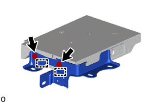
(b) Install the No. 2 navigation ECU bracket with the 2 bolts to the navigation ECU.
2. INSTALL NO. 1 NAVIGATION ECU BRACKET
|
(a) Engage the guides to temporarily install the No. 1 navigation ECU bracket. |
|
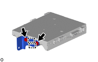
(b) Install the No. 1 navigation ECU bracket with the 2 bolts to the navigation ECU.
3. INSTALL ANTENNA CORD SUB-ASSEMBLY
|
(a) Engage the clamps to install the antenna cord sub-assembly. |
|
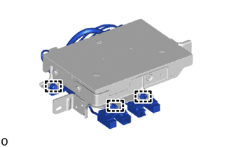
(b) Connect the 3 connectors.
4. INSTALL NAVIGATION ECU WITH BRACKET
(a) Connect the connector.
(b) Install the navigation ECU with bracket with the 2 nuts.
Torque:
12.0 N·m {122 kgf·cm, 9 ft·lbf}
(c) Connect the 4 connectors.
5. INSTALL INSTRUMENT CLUSTER FINISH LOWER CENTER PANEL SUB-ASSEMBLY
Click here
.gif)
6. INSTALL INSTRUMENT PANEL BOX ASSEMBLY
Click here
7. INSTALL INSTRUMENT PANEL LOWER CENTER FINISH PANEL
Click here
8. INSTALL NO. 1 INSTRUMENT PANEL UNDER COVER SUB-ASSEMBLY
Click here
9. INSTALL COWL SIDE TRIM BOARD LH
Click here
10. INSTALL FRONT DOOR SCUFF PLATE LH
Click here
11. INSTALL INSTRUMENT CLUSTER FINISH PANEL GARNISH ASSEMBLY
Click here
 Components
COMPONENTS
ILLUSTRATION
*1
COWL SIDE TRIM BOARD LH
*2
FRONT DOOR SCUFF PLATE LH
*3
INSTRUMENT CLUSTER FINISH LOWER CENTER PA ...
 Removal
REMOVAL
PROCEDURE
1. REMOVE INSTRUMENT CLUSTER FINISH PANEL GARNISH ASSEMBLY
Click here
2. REMOVE FRONT DOOR SCUFF PLATE LH
Click here
3. REMOVE COWL SIDE TRIM BOARD LH
Click here
...
Other materials:
Toyota CH-R Service Manual > Front Evaporator Temperature Sensor(for Valeo Made): Installation
INSTALLATION
PROCEDURE
1. INSTALL NO. 1 COOLER THERMISTOR
(a) Install the No. 1 cooler thermistor.
HINT:
Install the No. 1 cooler thermistor in the same area as the one that was previously
installed.
2. INSTALL NO. 1 COOLER EVAPORATOR SUB-ASSEMBLY
Click here
3. INSTALL RADIATOR CASE SU ...
Toyota CH-R Service Manual > Console Box Light: Inspection
INSPECTION
PROCEDURE
1. INSPECT INSTRUMENT CLUSTER FINISH PANEL GARNISH
(a) Check that the LED illuminates.
(1) Apply battery voltage to the instrument cluster finish panel garnish
and check that the LED illuminates.
OK:
Measurement Condition
...
Toyota C-HR (AX20) 2023-2026 Owner's Manual
Toyota CH-R Owners Manual
- For safety and security
- Instrument cluster
- Operation of each component
- Driving
- Interior features
- Maintenance and care
- When trouble arises
- Vehicle specifications
- For owners
Toyota CH-R Service Manual
- Introduction
- Maintenance
- Audio / Video
- Cellular Communication
- Navigation / Multi Info Display
- Park Assist / Monitoring
- Brake (front)
- Brake (rear)
- Brake Control / Dynamic Control Systems
- Brake System (other)
- Parking Brake
- Axle And Differential
- Drive Shaft / Propeller Shaft
- K114 Cvt
- 3zr-fae Battery / Charging
- Networking
- Power Distribution
- Power Assist Systems
- Steering Column
- Steering Gear / Linkage
- Alignment / Handling Diagnosis
- Front Suspension
- Rear Suspension
- Tire / Wheel
- Tire Pressure Monitoring
- Door / Hatch
- Exterior Panels / Trim
- Horn
- Lighting (ext)
- Mirror (ext)
- Window / Glass
- Wiper / Washer
- Door Lock
- Heating / Air Conditioning
- Interior Panels / Trim
- Lighting (int)
- Meter / Gauge / Display
- Mirror (int)
- Power Outlets (int)
- Pre-collision
- Seat
- Seat Belt
- Supplemental Restraint Systems
- Theft Deterrent / Keyless Entry

0.0081