Toyota CH-R Service Manual: Removal
REMOVAL
PROCEDURE
1. REMOVE INSTRUMENT CLUSTER FINISH PANEL GARNISH ASSEMBLY
Click here
.gif)
2. REMOVE FRONT DOOR SCUFF PLATE LH
Click here
3. REMOVE COWL SIDE TRIM BOARD LH
Click here
4. REMOVE NO. 1 INSTRUMENT PANEL UNDER COVER SUB-ASSEMBLY
Click here
5. REMOVE INSTRUMENT PANEL LOWER CENTER FINISH PANEL
Click here
6. REMOVE INSTRUMENT PANEL BOX ASSEMBLY
Click here
7. REMOVE INSTRUMENT CLUSTER FINISH LOWER CENTER PANEL SUB-ASSEMBLY
Click here
8. REMOVE NAVIGATION ECU WITH BRACKET
|
(a) Disconnect the 4 connectors. |
|
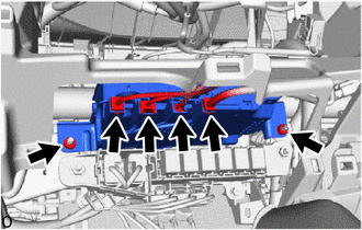
(b) Remove the 2 nuts and pull out the navigation ECU with bracket.
|
(c) Disconnect the connector to remove the navigation ECU with bracket. |
|
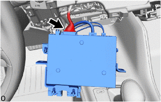
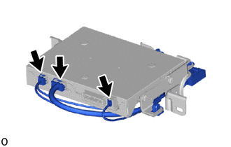
9. REMOVE ANTENNA CORD SUB-ASSEMBLY
|
(a) Disconnect the 3 connectors. |
|
|
(b) Disengage the clamps to remove the antenna cord sub-assembly. |
|
.png)
10. REMOVE NO. 1 NAVIGATION ECU BRACKET
.png)
(a) Remove the 2 bolts.
(b) Disengage the guides to remove the No. 1 navigation ECU bracket from the navigation ECU.
11. REMOVE NO. 2 NAVIGATION ECU BRACKET
|
(a) Remove the 2 bolts. |
|
.png)
(b) Disengage the guides to remove the No. 2 navigation ECU bracket from the navigation ECU.
 Installation
INSTALLATION
PROCEDURE
1. INSTALL NO. 2 NAVIGATION ECU BRACKET
(a) Engage the guides to temporarily install the No. 2 navigation ECU
bracket.
...

Other materials:
Toyota CH-R Service Manual > Rear Disc Brake Pad(for Tmc Made): Installation
INSTALLATION
CAUTION / NOTICE / HINT
NOTICE:
After replacing the rear disc brake pads, the brake pedal may feel soft due to
clearance between the rear disc brake pads and rear disc. Depress the brake pedal
several times until the brake pedal feels firm.
HINT:
The following procedure ...
Toyota CH-R Service Manual > Glove Box Light: Inspection
INSPECTION
PROCEDURE
1. INSPECT GLOVE BOX LIGHT ASSEMBLY
(a) Check that the LED illuminates.
(1) Apply battery voltage to the glove box light assembly and check that
the LED illuminates.
OK:
Measurement Condition
Specified Condition
...
Toyota C-HR (AX20) 2023-2026 Owner's Manual
Toyota CH-R Owners Manual
- For safety and security
- Instrument cluster
- Operation of each component
- Driving
- Interior features
- Maintenance and care
- When trouble arises
- Vehicle specifications
- For owners
Toyota CH-R Service Manual
- Introduction
- Maintenance
- Audio / Video
- Cellular Communication
- Navigation / Multi Info Display
- Park Assist / Monitoring
- Brake (front)
- Brake (rear)
- Brake Control / Dynamic Control Systems
- Brake System (other)
- Parking Brake
- Axle And Differential
- Drive Shaft / Propeller Shaft
- K114 Cvt
- 3zr-fae Battery / Charging
- Networking
- Power Distribution
- Power Assist Systems
- Steering Column
- Steering Gear / Linkage
- Alignment / Handling Diagnosis
- Front Suspension
- Rear Suspension
- Tire / Wheel
- Tire Pressure Monitoring
- Door / Hatch
- Exterior Panels / Trim
- Horn
- Lighting (ext)
- Mirror (ext)
- Window / Glass
- Wiper / Washer
- Door Lock
- Heating / Air Conditioning
- Interior Panels / Trim
- Lighting (int)
- Meter / Gauge / Display
- Mirror (int)
- Power Outlets (int)
- Pre-collision
- Seat
- Seat Belt
- Supplemental Restraint Systems
- Theft Deterrent / Keyless Entry

0.0081