Toyota CH-R Service Manual: Terminals Of Ecu
TERMINALS OF ECU
CHECK WINDSHIELD WIPER RELAY ASSEMBLY (w/ Rain Sensor)

(a) Disconnect the F56 windshield wiper relay assembly connector.
(1) Measure the voltage and resistance on the wire harness side connector according to the value(s) in the table below.
|
Terminal No. (Symbol) |
Wiring Color |
Terminal Description |
Condition |
Specified Condition |
|---|---|---|---|---|
|
F56-2 (IG) - Body ground |
B - Body ground |
Ignition switch ON signal (Power source circuit) |
Ignition switch ON |
11 to 14 V |
|
Ignition switch off |
Below 1 V |
|||
|
F56-25 (W) - Body ground |
B - Body ground |
Front washer switch signal |
Front washer switch on |
Below 1 Ω |
|
Front washer switch off |
10 kΩ or higher |
|||
|
F56-8 (VR2) - F56-21 (VR1) |
W - G |
Adjusting volume signal |
controlling sensitivity setting switch* changed |
0 to 231 Ω |
|
F56-12 (E) - Body ground |
W-B - Body ground |
Body ground |
Always |
Below 1 Ω |
|
F56-16 (WIG) - Body ground |
B - Body ground |
Power source signal |
Ignition switch ON |
11 to 14 V |
|
Ignition switch off |
Below 1 V |
HINT:
*: The rain sensor sensitivity can be adjusted by the controlling sensitivity setting switch.
If the result is not as specified, there may be a malfunction in the wire harness.
(b) Reconnect the F56 windshield wiper relay assembly connector.
(1) Measure the resistance according to the value(s) in the table below.
|
Terminal No. (Symbol) |
Wiring Color |
Terminal Description |
Condition |
Specified Condition |
|---|---|---|---|---|
|
F56-10 (+1) - Body ground |
G - Body ground |
Front wiper motor low speed signal |
Front wiper motor off |
Below 1 Ω |
HINT:
If the result is not as specified, the windshield wiper relay assembly may be malfunctioning.
(2) Measure the voltage and check for pulses according to the value(s) in the table below.
|
Terminal No. (Symbol) |
Wiring Color |
Terminal Description |
Condition |
Specified Condition |
|---|---|---|---|---|
|
F56-1 (+SM) - Body ground |
G - Body ground |
Front wiper motor position detection signal |
Front wiper motor in low or high operation |
Below 1 V ←→ 11 to 14 V |
|
Front wiper motor off |
Below 1 V |
|||
|
F56-3 (C1) - F56-5 (CO) |
V - Y |
Front wiper switch AUTO signal |
Ignition switch ON, front wiper switch in AUTO |
Below 1 V |
|
Ignition switch ON, front wiper switch off |
11 to 14 V |
|||
|
F56-25 (W) - Body ground |
B - Body ground |
Front washer switch signal |
Ignition switch ON, front washer switch on |
Below 1 V |
|
Ignition switch ON, front washer switch off |
11 to 14 V |
|||
|
F56-10 (+1) - Body ground |
G - Body ground |
Front wiper motor low speed signal |
Front wiper motor in low operation |
11 to 14 V |
|
F56-11 (+2) - Body ground |
W - Body ground |
Front wiper motor high speed signal |
Front wiper motor in high operation |
11 to 14 V |
|
Front wiper motor off |
Below 1 V |
|||
|
F56-14 (MPX1) - Body ground |
V - Body ground |
Rain sensor signal |
Ignition switch ON |
Pulse generation |
|
F56-24 (SPD) - Body ground |
V - Body ground |
Vehicle speed signal |
Driving at approximately 20 km/h (12 mph) |
Pulse generation (See waveform 1) |
HINT:
If the result is not as specified, the windshield wiper relay assembly may be malfunctioning.
(3) Waveform 1 (Reference):
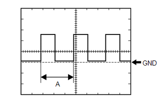
|
Item |
Condition |
|---|---|
|
Tester Connection |
F56-24 (SPD) - Body ground |
|
Tool Setting |
5 V/DIV., 20 ms./DIV. |
|
Vehicle Condition |
Driving at approximately 20 km/h (12 mph) |
HINT:
When the system is functioning normally, one wheel revolution generates 4 pulses. As the vehicle speed increases, the width indicated by A in the illustration narrows.
CHECK COMBINATION METER ASSEMBLY
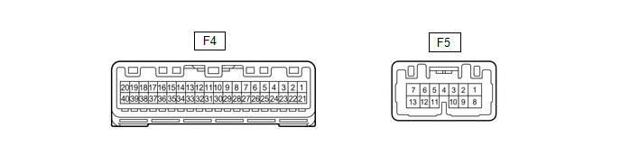
(a) Measure the voltage according to the value(s) in the table below.
|
Terminal No. (Symbol) |
Wiring Color |
Terminal Description |
Condition |
Specified Condition |
|---|---|---|---|---|
|
F4-17 (WLVL) - Body ground*1 |
LG - Body ground |
Washer fluid level signal |
Ignition switch ON, washer fluid level not low |
11 to 14 V |
|
Ignition switch ON, washer fluid level low |
Below 1 V |
- *1: for Cold Area Specification Vehicles
(b) Measure the waveform according to the value(s) in the table below.
|
Terminal No. (Symbol) |
Wiring Color |
Terminal Description |
Condition |
Specified Condition |
|---|---|---|---|---|
|
F4-6 (+S) - Body ground |
V - Body ground |
Speed signal for other system (Output) |
Driving at approximately 20 km/h (12 mph) |
Pulse generation (See waveform 1) |
(1) Waveform 1 (Reference):
|
Item |
Condition |
|---|---|
|
Tester Connection |
F4-6 (+S) - Body ground |
|
Tool Setting |
5 V/DIV., 20 ms./DIV. |
|
Vehicle Condition |
Driving at approximately 20 km/h (12 mph) |
HINT:
When the system is functioning normally, one wheel revolution generates 4 pulses. As the vehicle speed increases, the width indicated by A in the illustration narrows.
 Problem Symptoms Table
PROBLEM SYMPTOMS TABLE
HINT:
Use the table below to help determine the cause of problem symptoms. If multiple
suspected areas are listed, the potential causes of the symptoms are listed in order
...
 Fail-safe Chart
FAIL-SAFE CHART
RAIN SENSOR FAIL-SAFE FUNCTION
(a) The windshield wiper switch assembly performs the fail-safe function when
the wiper system cannot properly receive the necessary signals for wipe ...
Other materials:
Toyota CH-R Service Manual > Can Communication System: Radio Receiver Assembly Communication Stop Mode
DESCRIPTION
Detection Item
Symptom
Trouble Area
Radio Receiver Assembly Communication Stop Mode
Any of the following conditions are met:
Communication stop for "Display and Navigation (AVN)" is indicated
on t ...
Toyota CH-R Service Manual > Continuously Variable Transaxle System: Precaution
PRECAUTION
IGNITION SWITCH EXPRESSION
HINT:
The type of ignition switch used on this model differs depending on the specifications
of the vehicle. The expressions listed in the table below are used in this section.
Expression
Ignition Switch (Position)
Engine S ...
Toyota C-HR (AX20) 2023-2026 Owner's Manual
Toyota CH-R Owners Manual
- For safety and security
- Instrument cluster
- Operation of each component
- Driving
- Interior features
- Maintenance and care
- When trouble arises
- Vehicle specifications
- For owners
Toyota CH-R Service Manual
- Introduction
- Maintenance
- Audio / Video
- Cellular Communication
- Navigation / Multi Info Display
- Park Assist / Monitoring
- Brake (front)
- Brake (rear)
- Brake Control / Dynamic Control Systems
- Brake System (other)
- Parking Brake
- Axle And Differential
- Drive Shaft / Propeller Shaft
- K114 Cvt
- 3zr-fae Battery / Charging
- Networking
- Power Distribution
- Power Assist Systems
- Steering Column
- Steering Gear / Linkage
- Alignment / Handling Diagnosis
- Front Suspension
- Rear Suspension
- Tire / Wheel
- Tire Pressure Monitoring
- Door / Hatch
- Exterior Panels / Trim
- Horn
- Lighting (ext)
- Mirror (ext)
- Window / Glass
- Wiper / Washer
- Door Lock
- Heating / Air Conditioning
- Interior Panels / Trim
- Lighting (int)
- Meter / Gauge / Display
- Mirror (int)
- Power Outlets (int)
- Pre-collision
- Seat
- Seat Belt
- Supplemental Restraint Systems
- Theft Deterrent / Keyless Entry

0.0082