Toyota CH-R Service Manual: Components
COMPONENTS
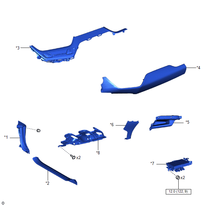
ILLUSTRATION
|
*1 |
COWL SIDE TRIM BOARD LH |
*2 |
FRONT DOOR SCUFF PLATE LH |
|
*3 |
INSTRUMENT CLUSTER FINISH LOWER CENTER PANEL SUB-ASSEMBLY |
*4 |
INSTRUMENT CLUSTER FINISH PANEL GARNISH ASSEMBLY |
|
*5 |
INSTRUMENT PANEL BOX ASSEMBLY |
*6 |
INSTRUMENT PANEL LOWER CENTER FINISH PANEL |
|
*7 |
NAVIGATION ECU WITH BRACKET |
*8 |
NO. 1 INSTRUMENT PANEL UNDER COVER SUB-ASSEMBLY |
.png) |
N*m (kgf*cm, ft.*lbf): Specified torque |
- |
- |
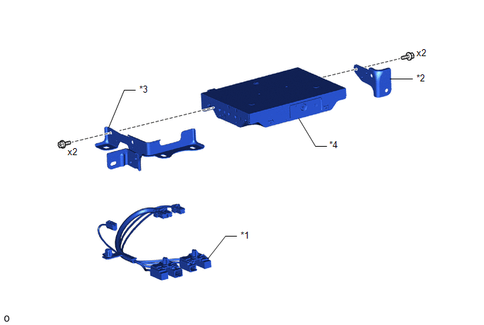
ILLUSTRATION
|
*1 |
ANTENNA CORD SUB-ASSEMBLY |
*2 |
NO. 1 NAVIGATION ECU BRACKET |
|
*3 |
NO. 2 NAVIGATION ECU BRACKET |
*4 |
NAVIGATION ECU |
 Navigation Ecu
...
 Installation
INSTALLATION
PROCEDURE
1. INSTALL NO. 2 NAVIGATION ECU BRACKET
(a) Engage the guides to temporarily install the No. 2 navigation ECU
bracket.
...
Other materials:
Toyota CH-R Service Manual > Wiper And Washer System: Data List / Active Test
DATA LIST / ACTIVE TEST
DATA LIST
HINT:
Using the Techstream to read the Data List allows the values or states of switches,
sensors, actuators and other items to be read without removing any parts. This non-intrusive
inspection can be very useful because intermittent conditions or signals may ...
Toyota CH-R Service Manual > Steering Gear: Reassembly
REASSEMBLY
PROCEDURE
1. INSTALL NO. 2 STEERING RACK BOOT
(a) Apply lithium soap base glycol grease to the inside of the small
opening of a new No. 2 steering rack boot.
(b) Install the No. 2 steering rack boot to the groove on the ra ...
Toyota C-HR (AX20) 2023-2026 Owner's Manual
Toyota CH-R Owners Manual
- For safety and security
- Instrument cluster
- Operation of each component
- Driving
- Interior features
- Maintenance and care
- When trouble arises
- Vehicle specifications
- For owners
Toyota CH-R Service Manual
- Introduction
- Maintenance
- Audio / Video
- Cellular Communication
- Navigation / Multi Info Display
- Park Assist / Monitoring
- Brake (front)
- Brake (rear)
- Brake Control / Dynamic Control Systems
- Brake System (other)
- Parking Brake
- Axle And Differential
- Drive Shaft / Propeller Shaft
- K114 Cvt
- 3zr-fae Battery / Charging
- Networking
- Power Distribution
- Power Assist Systems
- Steering Column
- Steering Gear / Linkage
- Alignment / Handling Diagnosis
- Front Suspension
- Rear Suspension
- Tire / Wheel
- Tire Pressure Monitoring
- Door / Hatch
- Exterior Panels / Trim
- Horn
- Lighting (ext)
- Mirror (ext)
- Window / Glass
- Wiper / Washer
- Door Lock
- Heating / Air Conditioning
- Interior Panels / Trim
- Lighting (int)
- Meter / Gauge / Display
- Mirror (int)
- Power Outlets (int)
- Pre-collision
- Seat
- Seat Belt
- Supplemental Restraint Systems
- Theft Deterrent / Keyless Entry

0.0076