Toyota CH-R Service Manual: Telephone Microphone Error (B1572)
DESCRIPTION
This DTC is set when the DCM (Telematics Transceiver) detects a malfunction in the telephone microphone assembly circuit.
|
DTC No. |
Detection Item |
DTC Detection Condition |
Trouble Area |
|---|---|---|---|
|
B1572 |
Telephone Microphone Error |
Current of MCVD reaches malfunction criteria for 10 seconds while ignition switch is ON. |
|
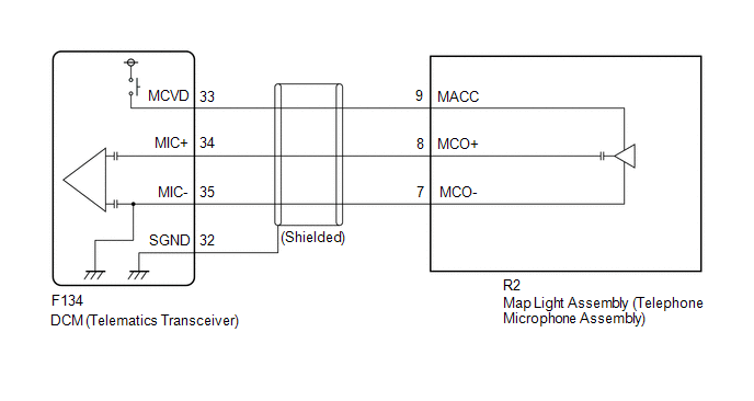
WIRING DIAGRAM
CAUTION / NOTICE / HINT
HINT:
Before performing this diagnostic procedure, make sure to perform Health Check and confirm that the DCM/VIN registration information is correct.
Click here
.gif)
PROCEDURE
|
1. |
CHECK DTC |
(a) Turn the ignition switch off.
(b) Connect the Techstream to the DLC3.
(c) Turn the ignition switch ON and wait for 10 seconds.
(d) Turn the Techstream on.
(e) Clear the DTCs.
Body Electrical > Telematics > Clear DTCs(f) Recheck for DTCs.
Body Electrical > Telematics > Trouble Codes|
Result |
Proceed to |
|---|---|
|
DTC B1572 is output |
A |
|
DTC B1572 is not output |
B |
| B | .gif) |
CHECK FOR INTERMITTENT PROBLEMS |
|
.gif)
|
2. |
INSPECT MAP LIGHT ASSEMBLY (TELEPHONE MICROPHONE ASSEMBLY POWER SOURCE) |
|
(a) Remove the map light assembly (telephone microphone assembly) but do not disconnect the connectors. Click here
|
|
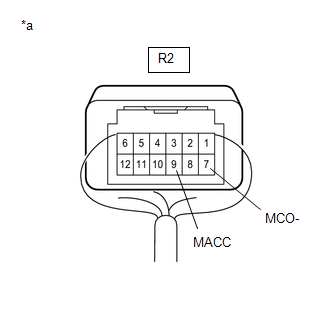
(b) Measure the voltage and resistance according to the value(s) in the table below.
Standard Voltage:
|
Tester Connection |
Switch Condition |
Specified Condition |
|---|---|---|
|
R2-9 (MACC) - Body ground |
Ignition switch ACC |
4 to 6 V |
Standard Resistance:
|
Tester Connection |
Condition |
Specified Condition |
|---|---|---|
|
R2-7 (MCO-) - Body ground |
Always |
Below 1 Ω |
| NG | |
GO TO STEP 4 |
|
|
3. |
CHECK HARNESS AND CONNECTOR (DCM (TELEMATICS TRANSCEIVER) - MAP LIGHT ASSEMBLY (TELEPHONE MICROPHONE ASSEMBLY)) |
(a) Disconnect the F134 DCM (Telematics Transceiver) connector.
(b) Disconnect the R2 map light assembly (telephone microphone assembly) connector.
(c) Measure the resistance according to the value(s) in the table below.
Standard Resistance:
|
Tester Connection |
Condition |
Specified Condition |
|---|---|---|
|
F134-34 (MIC+) - R2-8 (MCO+) |
Always |
Below 1 Ω |
|
F134-34 (MIC+) or R2-8 (MCO+) - Body ground |
Always |
10 kΩ or higher |
|
F134-35 (MIC-) - R2-7 (MCO-) |
Always |
Below 1 Ω |
|
F134-35 (MIC-) or R2-7 (MCO-) - Body ground |
Always |
10 kΩ or higher |
|
F134-32 (SGND) - Body ground |
Always |
10 kΩ or higher |
| OK | |
REPLACE MAP LIGHT ASSEMBLY (TELEPHONE MICROPHONE ASSEMBLY) |
| NG | |
REPAIR OR REPLACE HARNESS OR CONNECTOR |
|
4. |
INSPECT DCM (TELEMATICS TRANSCEIVER) (TELEPHONE MICROPHONE ASSEMBLY POWER SOURCE) |
|
(a) Remove the DCM (Telematics Transceiver) but do not disconnect the connectors. Click here
|
|
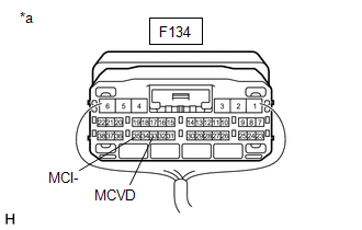
(b) Measure the voltage and resistance according to the value(s) in the table below.
Standard Voltage:
|
Tester Connection |
Switch Condition |
Specified Condition |
|---|---|---|
|
F134-33 (MCVD) - Body ground |
Ignition switch ACC |
4 to 6 V |
Standard Resistance:
|
Tester Connection |
Condition |
Specified Condition |
|---|---|---|
|
F134-35 (MCI-) - Body ground |
Always |
Below 1 Ω |
| OK | |
REPAIR OR REPLACE HARNESS OR CONNECTOR |
|
|
5. |
REPLACE DCM (TELEMATICS TRANSCEIVER) |
(a) Replace the DCM (Telematics Transceiver).
Click here
NOTICE:
- The ignition switch must be off.
- Do not swap the DCM (Telematics Transceiver) with one from another vehicle.
| NEXT | |
PERFORM DCM ACTIVATION |
 Ignition Switch Signal Malfunction (B15C6)
DESCRIPTION
If vehicle movement (10 km/h (6 mph) or more for 10 seconds) is detected based
on the location data sent from the radio receiver assembly even when the telematics
transceiver detects ...
 Backup Battery Degradation (B15EC)
DESCRIPTION
This DTC is set when the DCM (Telematics Transceiver) detects either of the following
conditions.
The BUB (Back-Up Battery) charge level becomes less than the criteria.
T ...
Other materials:
Toyota CH-R Service Manual > Wireless Door Lock Control System(w/ Smart Key System): How To Proceed With Troubleshooting
CAUTION / NOTICE / HINT
HINT:
The wireless door lock control system troubleshooting procedure is based
on the premise that the power door lock control system is operating properly.
Check the power door lock control system first before troubleshooting the
wireless door lock cont ...
Toyota CH-R Service Manual > Front Seatback Heater: Installation
INSTALLATION
CAUTION / NOTICE / HINT
CAUTION:
Be sure to read Precaution thoroughly before servicing.
Click here
Wear protective gloves. Sharp areas on the parts may injure your hands.
HINT:
Use the same procedure for the driver side and front passen ...
Toyota C-HR (AX20) 2023-2026 Owner's Manual
Toyota CH-R Owners Manual
- For safety and security
- Instrument cluster
- Operation of each component
- Driving
- Interior features
- Maintenance and care
- When trouble arises
- Vehicle specifications
- For owners
Toyota CH-R Service Manual
- Introduction
- Maintenance
- Audio / Video
- Cellular Communication
- Navigation / Multi Info Display
- Park Assist / Monitoring
- Brake (front)
- Brake (rear)
- Brake Control / Dynamic Control Systems
- Brake System (other)
- Parking Brake
- Axle And Differential
- Drive Shaft / Propeller Shaft
- K114 Cvt
- 3zr-fae Battery / Charging
- Networking
- Power Distribution
- Power Assist Systems
- Steering Column
- Steering Gear / Linkage
- Alignment / Handling Diagnosis
- Front Suspension
- Rear Suspension
- Tire / Wheel
- Tire Pressure Monitoring
- Door / Hatch
- Exterior Panels / Trim
- Horn
- Lighting (ext)
- Mirror (ext)
- Window / Glass
- Wiper / Washer
- Door Lock
- Heating / Air Conditioning
- Interior Panels / Trim
- Lighting (int)
- Meter / Gauge / Display
- Mirror (int)
- Power Outlets (int)
- Pre-collision
- Seat
- Seat Belt
- Supplemental Restraint Systems
- Theft Deterrent / Keyless Entry

0.0142