Toyota CH-R Service Manual: Antenna Coil Open / Short (B2784)
DESCRIPTION
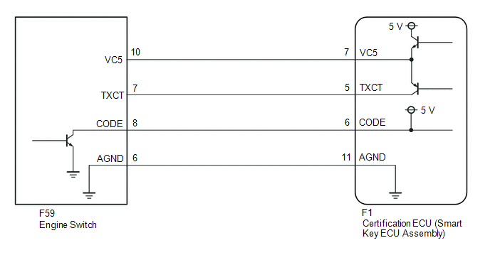
When an open or short circuit is detected in the transponder key amplifier coil built into the engine switch, the certification ECU (smart key ECU assembly) stores this DTC. This DTC is also stored as a history DTC.
|
DTC No. |
Detection Item |
DTC Detection Condition |
Trouble Area |
Note |
|---|---|---|---|---|
|
B2784 |
Antenna Coil Open / Short |
When either of the following conditions is met (1-trip detection logic*1):
|
|
DTC output confirmation operation:
|
- *1: Only output while a malfunction is present.
|
Vehicle Condition |
|||
|---|---|---|---|
|
Pattern 1 |
Pattern 2 |
||
|
Diagnosis Condition |
Always |
○ |
○ |
|
Malfunction Status |
The transponder key amplifier coil built into the engine switch is open (determined by communication with certification ECU (smart key ECU assembly)). |
○ |
- |
|
The transponder key amplifier coil built into the engine switch is shorted (determined by communication with certification ECU (smart key ECU assembly)). |
- |
○ |
|
|
Detection Time |
- |
- |
|
|
Number of Trips |
1 trip |
1 trip |
|
|
Vehicle Condition when Malfunction Detected |
Fail-safe Operation when Malfunction Detected |
|---|---|
|
Engine cannot be started when transmitter battery is depleted by holding electrical key transmitter sub-assembly near engine switch and pressing and holding engine switch with shift lever in P |
- |
|
DTC No. |
Data List and Active Test |
|---|---|
|
B2784 |
- |
WIRING DIAGRAM
CAUTION / NOTICE / HINT
NOTICE:
- When using the Techstream with the engine switch off, connect the Techstream to the DLC3 and turn a courtesy light switch on and off at intervals of 1.5 seconds or less until communication between the Techstream and the vehicle begins. Then select the vehicle type under manual mode and enter the following menus: Body Electrical / Smart Key. While using the Techstream, periodically turn a courtesy light switch on and off at intervals of 1.5 seconds or less to maintain communication between the Techstream and the vehicle.
- Before replacing the certification ECU (smart key ECU assembly), refer
to Registration.
Click here
.gif)
- After performing repairs, confirm that no DTCs are output by performing "DTC Output Confirmation Operation".
PROCEDURE
|
1. |
CLEAR DTC |
(a) Clear the DTCs.
Click here
|
.gif)
|
2. |
CHECK FOR DTC |
(a) Perform "DTC Output Confirmation Operation" procedure.
(b) Check for DTCs.
Click here
OK:
DTC B2784 is not output.
| OK | .gif) |
USE SIMULATION METHOD TO CHECK |
|
|
3. |
CHECK ENGINE SWITCH (OUTPUT) |
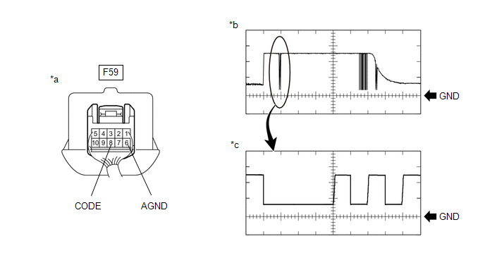
(a) Using an oscilloscope, check the waveform.
|
*a |
Component with harness connected (Engine Switch) |
*b |
Waveform |
|
*c |
Waveform (detail) |
- |
- |
Measurement Condition:
|
Tester Connection |
Condition |
Tool Setting |
Specified Condition |
|---|---|---|---|
|
F59-8 (CODE) - F59-6 (AGND) |
Engine switch off, engine switch pressed with electrical key transmitter sub-assembly held near engine switch* |
1 V/DIV., 20 ms./DIV. |
Pulse generation (See waveform) |
|
2 V/DIV., 100 μs./DIV. |
Pulse generation (See waveform (detail)) |
- *: Remove the transmitter battery before performing this inspection.
OK:
The waveform is similar to that shown in the illustration
| NG | |
REPLACE ENGINE SWITCH |
|
|
4. |
REPLACE CERTIFICATION ECU (SMART KEY ECU ASSEMBLY) |
(a) Replace the certification ECU (smart key ECU assembly) with a new one.
Click here
|
|
5. |
REGISTER ECU COMMUNICATION ID |
(a) Register the ECU communication ID code.
Click here
|
|
6. |
CLEAR DTC |
(a) Clear the DTCs.
Click here
|
|
7. |
CHECK FOR DTC |
(a) Perform "DTC Output Confirmation Operation" procedure.
(b) Check for DTCs.
Click here
OK:
DTC B2784 is not output.
| OK | |
END (CERTIFICATION ECU (SMART KEY ECU ASSEMBLY) WAS DEFECTIVE) |
| NG | |
REPLACE ENGINE SWITCH |
 Short to GND in Immobiliser System Power Source Circuit (B278A)
DESCRIPTION
When there is a short to GND in the power supply for the transponder key amplifier
of the engine switch, the certification ECU (smart key ECU assembly) stores this
DTC.
DT ...
 Theft Deterrent System Communication Line High Fixation (B279A)
DESCRIPTION
If the communication line (IMI - EFIO) between the ECM and ID code box (immobiliser
code ECU) is stuck high, the ECM will store this DTC.
DTC No.
Detection Item
...
Other materials:
Toyota CH-R Owners Manual > Air conditioning system: Air conditioning controls
■ Adjusting the temperature setting
Increases the temperature
Decreases the temperature
If the
indicator
is turned off, the system will blow ambient temperature air or heated air.
■ Fan speed setting
Increases the fan speed
Decreases the fan speed
Press
to
turn t ...
Toyota CH-R Service Manual > Can Communication System: DCM Communication Stop Mode
DESCRIPTION
Detection Item
Symptom
Trouble Area
DCM Communication Stop Mode
Any of the following conditions are met:
Communication stop for "DCM" is indicated on the "Communication
Bus Check" screen ...
Toyota C-HR (AX20) 2023-2026 Owner's Manual
Toyota CH-R Owners Manual
- For safety and security
- Instrument cluster
- Operation of each component
- Driving
- Interior features
- Maintenance and care
- When trouble arises
- Vehicle specifications
- For owners
Toyota CH-R Service Manual
- Introduction
- Maintenance
- Audio / Video
- Cellular Communication
- Navigation / Multi Info Display
- Park Assist / Monitoring
- Brake (front)
- Brake (rear)
- Brake Control / Dynamic Control Systems
- Brake System (other)
- Parking Brake
- Axle And Differential
- Drive Shaft / Propeller Shaft
- K114 Cvt
- 3zr-fae Battery / Charging
- Networking
- Power Distribution
- Power Assist Systems
- Steering Column
- Steering Gear / Linkage
- Alignment / Handling Diagnosis
- Front Suspension
- Rear Suspension
- Tire / Wheel
- Tire Pressure Monitoring
- Door / Hatch
- Exterior Panels / Trim
- Horn
- Lighting (ext)
- Mirror (ext)
- Window / Glass
- Wiper / Washer
- Door Lock
- Heating / Air Conditioning
- Interior Panels / Trim
- Lighting (int)
- Meter / Gauge / Display
- Mirror (int)
- Power Outlets (int)
- Pre-collision
- Seat
- Seat Belt
- Supplemental Restraint Systems
- Theft Deterrent / Keyless Entry

0.0105