Toyota CH-R Service Manual: Short to GND in Immobiliser System Power Source Circuit (B278A)
DESCRIPTION
When there is a short to GND in the power supply for the transponder key amplifier of the engine switch, the certification ECU (smart key ECU assembly) stores this DTC.
|
DTC No. |
Detection Item |
DTC Detection Condition |
Trouble Area |
Note |
|---|---|---|---|---|
|
B278A |
Short to GND in Immobiliser System Power Source Circuit |
A short to GND in the power supply of the transponder key amplifier of the engine switch (VC5 - VC5) detected. (1 trip detection logic*1) |
|
DTC output confirmation operation:
|
- *1: Only output while a malfunction is present.
|
Vehicle Condition when Malfunction Detected |
Fail-safe Operation when Malfunction Detected |
|---|---|
|
Engine cannot be started when transmitter battery is depleted by holding transmitter near engine switch and pressing and holding engine switch with shift lever in P |
- |
|
DTC No. |
Data List and Active Test |
|---|---|
|
B278A |
- |
WIRING DIAGRAM
Refer to B2784.
Click here .gif)
CAUTION / NOTICE / HINT
NOTICE:
- When using the Techstream with the engine switch off, connect the Techstream to the DLC3 and turn a courtesy light switch on and off at intervals of 1.5 seconds or less until communication between the Techstream and the vehicle begins. Then select the vehicle type under manual mode and enter the following menus: Body Electrical / Smart Key. While using the Techstream, periodically turn a courtesy light switch on and off at intervals of 1.5 seconds or less to maintain communication between the Techstream and the vehicle.
- Before replacing the certification ECU (smart key ECU assembly), refer
to Registration.
Click here
- After performing repairs, confirm that no DTCs are output by performing "DTC Output Confirmation Operation".
PROCEDURE
|
1. |
CHECK CERTIFICATION ECU (SMART KEY ECU ASSEMBLY) |
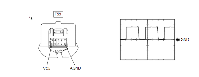
(a) Using an oscilloscope, check the waveform.
|
*a |
Component with harness connected (Engine Switch) |
- |
- |
HINT:
Perform this inspection on the engine switch side.
Measurement Condition:
|
Tester Connection |
Condition |
Tool Setting |
Specified Condition |
|---|---|---|---|
|
F59-10 (VC5) - F59-6 (AGND) |
Engine switch off, electrical key transmitter sub-assembly not in cabin, within 30 seconds of engine switch pressed |
2 V/DIV., 200 ms./DIV. |
Pulse generation |
OK:
The waveform is similar to that shown in the illustration.
| OK | .gif) |
REPLACE ENGINE SWITCH |
|
.gif)
|
2. |
CHECK HARNESS AND CONNECTOR (CERTIFICATION ECU (SMART KEY ECU ASSEMBLY) - ENGINE SWITCH) |
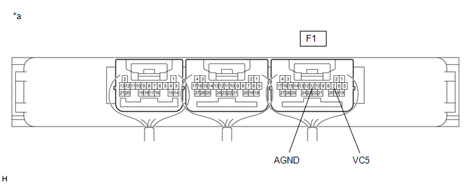
(a) Disconnect the F1 certification ECU (smart key ECU assembly) connector.
(b) Disconnect the F59 engine switch connector.
(c) Measure the resistance according to the value(s) in the table below.
Standard Resistance:
|
Tester Connection |
Condition |
Specified Condition |
|---|---|---|
|
F1-7 (VC5) - F59-10 (VC5) |
Always |
Below 1 Ω |
|
F1-11 (AGND) - F59-6 (AGND) |
Always |
Below 1 Ω |
|
F1-7 (VC5) or F59-10 (VC5) - Body ground |
Always |
10 kΩ or higher |
|
F1-11 (AGND) or F59-6 (AGND) - Body ground |
Always |
10 kΩ or higher |
| NG | |
REPAIR OR REPLACE HARNESS OR CONNECTOR |
|
|
3. |
CHECK CERTIFICATION ECU (SMART KEY ECU ASSEMBLY) |
(a) Reconnect the F1 certification ECU (smart key ECU assembly) connector.
(b) Reconnect the F59 engine switch connector.
(c) Measure the voltage according to the value(s) in the table below.
|
*a |
Component with harness connected (Certification ECU (Smart Key ECU Assembly)) |
- |
- |
Standard Voltage:
|
Tester Connection |
Condition |
Specified Condition |
|---|---|---|
|
F1-7 (VC5) - F1-11 (AGND) |
Engine switch off, brake pedal not depressed, 30 seconds or more after driver door opened and then closed |
Below 1 V |
| OK | |
REPLACE ENGINE SWITCH |
| NG | |
REPLACE CERTIFICATION ECU (SMART KEY ECU ASSEMBLY) |
 ID BOX EEPROM Malfunction (B2790)
DESCRIPTION
When an internal malfunction occurs in the ID code box (immobiliser code ECU),
the certification ECU (smart key ECU assembly) stores this DTC.
DTC No.
Detection I ...
 Antenna Coil Open / Short (B2784)
DESCRIPTION
When an open or short circuit is detected in the transponder key amplifier coil
built into the engine switch, the certification ECU (smart key ECU assembly) stores
this DTC. This DTC ...
Other materials:
Toyota CH-R Service Manual > Power Window Control System: Rear Power Window LH Auto Up / Down Function does not Operate with Rear Power
Window Switch LH
DESCRIPTION
If the manual up and down functions operate normally but the auto up and down
functions do not, the power window control system may be in fail-safe mode.
If power window initialization has not been performed, the auto up and down functions
will not operate.
Click here
WIRING ...
Toyota CH-R Owners Manual > Side doors: Unlocking and locking the doors from the inside
Door lock switches
Locks all the doors
Unlocks all the doors
Inside lock buttons
Locks the door
Unlocks the door
The front doors can be opened by pulling the inside handle even if the lock buttons
are in the lock position.
Locking the doors from the outside without a key ...
Toyota C-HR (AX20) 2023-2026 Owner's Manual
Toyota CH-R Owners Manual
- For safety and security
- Instrument cluster
- Operation of each component
- Driving
- Interior features
- Maintenance and care
- When trouble arises
- Vehicle specifications
- For owners
Toyota CH-R Service Manual
- Introduction
- Maintenance
- Audio / Video
- Cellular Communication
- Navigation / Multi Info Display
- Park Assist / Monitoring
- Brake (front)
- Brake (rear)
- Brake Control / Dynamic Control Systems
- Brake System (other)
- Parking Brake
- Axle And Differential
- Drive Shaft / Propeller Shaft
- K114 Cvt
- 3zr-fae Battery / Charging
- Networking
- Power Distribution
- Power Assist Systems
- Steering Column
- Steering Gear / Linkage
- Alignment / Handling Diagnosis
- Front Suspension
- Rear Suspension
- Tire / Wheel
- Tire Pressure Monitoring
- Door / Hatch
- Exterior Panels / Trim
- Horn
- Lighting (ext)
- Mirror (ext)
- Window / Glass
- Wiper / Washer
- Door Lock
- Heating / Air Conditioning
- Interior Panels / Trim
- Lighting (int)
- Meter / Gauge / Display
- Mirror (int)
- Power Outlets (int)
- Pre-collision
- Seat
- Seat Belt
- Supplemental Restraint Systems
- Theft Deterrent / Keyless Entry

0.0079