Toyota CH-R Service Manual: Driver Side Seat Belt Warning Light does not Operate
DESCRIPTION
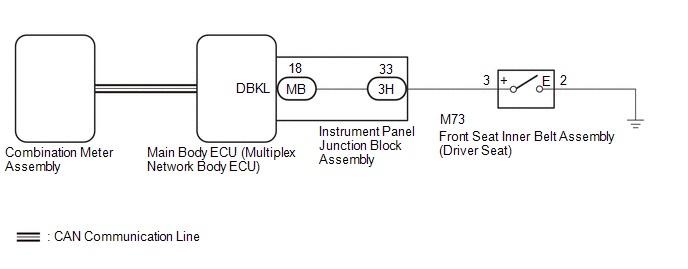
The combination meter assembly blinks or turns off the seat belt warning light on the combination meter assembly in accordance with the state of the front seat inner belt assembly (driver seat).
WIRING DIAGRAM
CAUTION / NOTICE / HINT
NOTICE:
- The seat belt warning system uses the CAN communication system. First,
confirm that there is no malfunction in the CAN communication system. Refer
to the How to Proceed with Troubleshooting procedure.
Click here
.gif)
- When replacing the combination meter assembly, always replace it with a new one. If a combination meter assembly which was installed to another vehicle is used, the information stored in it will not match the information from the vehicle and a DTC may be stored.
- Before replacing the main body ECU (multiplex network body ECU), refer
to Registration.*1
*1: w/ Smart key System
Click here
HINT:
- The seat belt warning light on the combination meter assembly is used
for both the driver seat and front passenger seat. Check that the operation
of the seat belt warning light is normal first.
Click here
- If the seat belt warning light does not operate for both the driver
seat and front passenger seat, replace the combination meter assembly.
Click here
PROCEDURE
|
1. |
READ VALUE USING TECHSTREAM |
(a) Connect the Techstream to the DLC3.
(b) Turn the ignition switch to ON.
(c) Turn the Techstream on.
(d) Enter the following menus: Body Electrical / Main Body / Data List.
(e) Read the Data List according to the display on the Techstream.
Body Electrical > Main Body > Data List|
Tester Display |
Measurement Item |
Range |
Normal Condition |
Diagnostic Note |
|---|---|---|---|---|
|
D Seat Buckle SW |
Driver seat belt buckle switch |
ON or OFF |
ON: Driver seat belt unfastened OFF: Driver seat belt fastened |
- |
|
Tester Display |
|---|
|
D Seat Buckle SW |
OK:
ON or OFF appears on the Techstream screen according to the driver seat belt condition.
| OK | .gif) |
REPLACE MAIN BODY ECU (MULTIPLEX NETWORK BODY ECU) |
|
.gif)
|
2. |
INSPECT FRONT SEAT INNER BELT ASSEMBLY (DRIVER SEAT) |
(a) Remove the front seat inner belt assembly (driver seat).
Click here
(b) Inspect the front seat inner belt assembly (driver seat) (seat belt warning switch).
Click here
| NG | |
REPLACE FRONT SEAT INNER BELT ASSEMBLY (DRIVER SEAT) |
|
|
3. |
INSPECT INSTRUMENT PANEL JUNCTION BLOCK ASSEMBLY |
(a) Remove the main body ECU (multiplex network body ECU).
Click here
|
*a |
Component without harness connected (Instrument Panel Junction Block Assembly) |
- |
- |
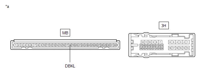
(b) Disconnect the 3H instrument panel junction block assembly connector.
(c) Measure the resistance according to the value(s) in the table below.
Standard Resistance:
|
Tester Connection |
Condition |
Specified Condition |
|---|---|---|
|
MB-18 (DBKL) - 3H-33 |
Always |
Below 1 Ω |
| NG | |
REPLACE INSTRUMENT PANEL JUNCTION BLOCK ASSEMBLY |
|
|
4. |
CHECK HARNESS AND CONNECTOR (MAIN BODY ECU (MULTIPLEX NETWORK BODY ECU) - FRONT SEAT INNER BELT ASSEMBLY (DRIVER SEAT) - BODY GROUND) |
(a) Measure the resistance according to the value(s) in the table below.
Standard Resistance:
|
Tester Connection |
Condition |
Specified Condition |
|---|---|---|
|
3H-33 - M73-3 (+) |
Always |
Below 1 Ω |
|
M73-3 (+) - Body ground |
Always |
10 kΩ or higher |
|
M73-2 (E) - Body ground |
Always |
Below 1 Ω |
| OK | |
REPLACE MAIN BODY ECU (MULTIPLEX NETWORK BODY ECU) |
| NG | |
REPAIR OR REPLACE HARNESS OR CONNECTOR |
 Terminals Of Ecu
TERMINALS OF ECU
CHECK MAIN BODY ECU (MULTIPLEX NETWORK BODY ECU) AND INSTRUMENT PANEL JUNCTION
BLOCK ASSEMBLY
*A
Main Body ECU (Multiplex Network Body ECU) with 1 Connecto ...
 On-vehicle Inspection
ON-VEHICLE INSPECTION
PROCEDURE
1. INSPECT DRIVER SEAT BELT WARNING SYSTEM
HINT:
The seat belt warning light on the combination meter assembly is used for both
the driver seat and front passenge ...
Other materials:
Toyota CH-R Service Manual > Navigation System: Problem Symptoms Table
PROBLEM SYMPTOMS TABLE
NOTICE:
Depending on the parts that are replaced during vehicle inspection or
maintenance, performing initialization, registration or calibration may
be needed. Refer to Precaution for Navigation System.
Click here
When replacing the radio a ...
Toyota CH-R Service Manual > Rear Door Lock: Components
COMPONENTS
ILLUSTRATION
*1
REAR DOOR INSIDE HANDLE BEZEL PLUG
*2
REAR DOOR REAR FRAME BRACKET
*3
REAR DOOR TRIM BOARD SUB-ASSEMBLY
*4
REAR POWER WINDOW REGULATOR SWITCH ASSEMBLY WITH REAR DOOR ARMREST B ...
Toyota C-HR (AX20) 2023-2026 Owner's Manual
Toyota CH-R Owners Manual
- For safety and security
- Instrument cluster
- Operation of each component
- Driving
- Interior features
- Maintenance and care
- When trouble arises
- Vehicle specifications
- For owners
Toyota CH-R Service Manual
- Introduction
- Maintenance
- Audio / Video
- Cellular Communication
- Navigation / Multi Info Display
- Park Assist / Monitoring
- Brake (front)
- Brake (rear)
- Brake Control / Dynamic Control Systems
- Brake System (other)
- Parking Brake
- Axle And Differential
- Drive Shaft / Propeller Shaft
- K114 Cvt
- 3zr-fae Battery / Charging
- Networking
- Power Distribution
- Power Assist Systems
- Steering Column
- Steering Gear / Linkage
- Alignment / Handling Diagnosis
- Front Suspension
- Rear Suspension
- Tire / Wheel
- Tire Pressure Monitoring
- Door / Hatch
- Exterior Panels / Trim
- Horn
- Lighting (ext)
- Mirror (ext)
- Window / Glass
- Wiper / Washer
- Door Lock
- Heating / Air Conditioning
- Interior Panels / Trim
- Lighting (int)
- Meter / Gauge / Display
- Mirror (int)
- Power Outlets (int)
- Pre-collision
- Seat
- Seat Belt
- Supplemental Restraint Systems
- Theft Deterrent / Keyless Entry

0.0083