Toyota CH-R Service Manual: Terminals Of Ecu
TERMINALS OF ECU
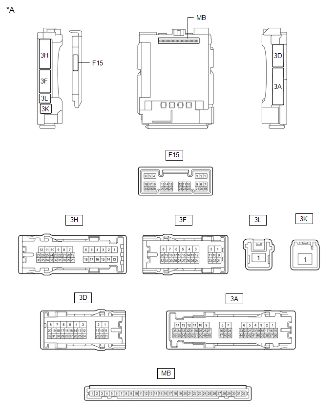
CHECK MAIN BODY ECU (MULTIPLEX NETWORK BODY ECU) AND INSTRUMENT PANEL JUNCTION BLOCK ASSEMBLY
|
*A |
Main Body ECU (Multiplex Network Body ECU) with 1 Connector |
- |
- |
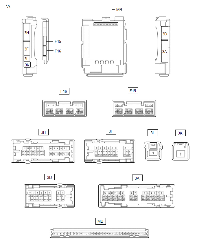
|
*A |
Main Body ECU (Multiplex Network Body ECU) with 2 Connectors |
- |
- |
(a) Disconnect the main body ECU (multiplex network body ECU) connectors.
Click here .gif)
(b) Measure the resistance and voltage according to the value(s) in the table below.
HINT:
Measure the values on the wire harness side with the connector disconnected.
|
Terminal No. (Symbol) |
Wiring Color |
Terminal Description |
Condition |
Specified Condition |
|---|---|---|---|---|
|
MB-31 (BECU) - Body ground |
- |
Battery power supply |
Always |
11 to 14 V |
|
MB-32 (IG) - Body ground |
- |
Ignition power supply (IG signal) |
Ignition switch ON → off |
11 to 14 V → Below 1 V |
|
MB-30 (ACC) - Body ground |
- |
Ignition power supply (ACC signal) |
Ignition switch ACC → off |
11 to 14 V → Below 1 V |
|
MB-11 (GND1) - Body ground |
- |
Ground |
Always |
Below 1 Ω |
|
MB-18 (DBKL) - Body ground |
- |
Driver seat belt buckle switch signal |
Driver seat belt fastened |
10 kΩ or higher |
|
Driver seat belt unfastened |
Below 1 Ω |
|||
|
MB-2 (RCTY) - Body ground |
- |
Rear door courtesy light switch RH input |
Rear door LH closed (OFF) |
10 kΩ or higher |
|
Rear door LH open (ON) |
Below 1 Ω |
|||
|
MB-13 (LCTY) - Body ground |
- |
Rear door courtesy light switch LH input |
Rear door RH closed (OFF) |
10 kΩ or higher |
|
Rear door RH open (ON) |
Below 1 Ω |
CHECK COMBINATION METER ASSEMBLY

(a) Disconnect the F4 combination meter assembly connector.
(b) Measure the resistance and voltage according to the value(s) in the table below.
HINT:
Measure the values on the wire harness side with the connector disconnected.
|
Terminal No. (Symbol) |
Wiring Color |
Terminal Description |
Condition |
Specified Condition |
|---|---|---|---|---|
|
F4-40 (B) - Body ground |
SB - Body ground |
Battery power supply |
Always |
11 to 14 V |
|
F4-39 (IG+) - Body ground |
P - Body ground |
IG power supply |
Ignition switch ON → off |
11 to 14 V → Below 1 V |
|
F4-21 (ET) - Body ground |
W- B - Body ground |
Ground |
Always |
Below 1 Ω |
|
F4-7 (PKBI) - Body ground |
GR - Body ground |
Front passenger seat belt buckle switch signal |
Ignition switch ON, front passenger side seat belt fastened and front passenger seat occupied |
10 kΩ or higher |
|
Ignition switch ON, front passenger side seat belt unfastened and front passenger seat occupied |
Below 1 Ω |
 Data List / Active Test
DATA LIST / ACTIVE TEST
DATA LIST
NOTICE:
In the following table, the values listed under "Normal Condition" are reference
values. Do not depend solely on these reference values when de ...
 Driver Side Seat Belt Warning Light does not Operate
DESCRIPTION
The combination meter assembly blinks or turns off the seat belt warning light
on the combination meter assembly in accordance with the state of the front seat
inner belt assembly (dr ...
Other materials:
Toyota CH-R Service Manual > Front Door Window Frame Moulding: Components
COMPONENTS
ILLUSTRATION
*A
for TMMT Made
*B
for TMC Made
*1
DOOR FRAME UPPER GARNISH
*2
FRONT DOOR FIX WINDOW GLASS
*3
FRONT DOOR FRONT LOWER FRAME SUB-ASSEMBLY
*4 ...
Toyota CH-R Service Manual > Brake Pedal: Components
COMPONENTS
ILLUSTRATION
*1
BRAKE PEDAL PAD
*2
BRAKE PEDAL RETURN SPRING
*3
BRAKE PEDAL SUPPORT ASSEMBLY
*4
PUSH ROD PIN
*5
STOP LIGHT SWITCH MOUNTING ADJUSTER
*6
...
Toyota C-HR (AX20) 2023-2026 Owner's Manual
Toyota CH-R Owners Manual
- For safety and security
- Instrument cluster
- Operation of each component
- Driving
- Interior features
- Maintenance and care
- When trouble arises
- Vehicle specifications
- For owners
Toyota CH-R Service Manual
- Introduction
- Maintenance
- Audio / Video
- Cellular Communication
- Navigation / Multi Info Display
- Park Assist / Monitoring
- Brake (front)
- Brake (rear)
- Brake Control / Dynamic Control Systems
- Brake System (other)
- Parking Brake
- Axle And Differential
- Drive Shaft / Propeller Shaft
- K114 Cvt
- 3zr-fae Battery / Charging
- Networking
- Power Distribution
- Power Assist Systems
- Steering Column
- Steering Gear / Linkage
- Alignment / Handling Diagnosis
- Front Suspension
- Rear Suspension
- Tire / Wheel
- Tire Pressure Monitoring
- Door / Hatch
- Exterior Panels / Trim
- Horn
- Lighting (ext)
- Mirror (ext)
- Window / Glass
- Wiper / Washer
- Door Lock
- Heating / Air Conditioning
- Interior Panels / Trim
- Lighting (int)
- Meter / Gauge / Display
- Mirror (int)
- Power Outlets (int)
- Pre-collision
- Seat
- Seat Belt
- Supplemental Restraint Systems
- Theft Deterrent / Keyless Entry

0.0102