Toyota CH-R Service Manual: Theft Deterrent System Communication Line High Fixation (B279A)
DESCRIPTION
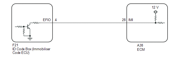
If the communication line (IMI - EFIO) between the ECM and ID code box (immobiliser code ECU) is stuck high, the ECM will store this DTC.
|
DTC No. |
Detection Item |
DTC Detection Condition |
Trouble Area |
Note |
|---|---|---|---|---|
|
B279A |
Theft Deterrent System Communication Line High Fixation |
The communication line (IMI - EFIO) between the ECM and ID code box (immobiliser code ECU) is stuck high. (1 trip detection logic*) |
|
DTC output confirmation operation:
|
- *: Only output while a malfunction is present.
|
Vehicle Condition when Malfunction Detected |
Fail-safe Operation when Malfunction Detected |
|---|---|
|
Engine cannot be started |
Engine cannot be started |
|
DTC No. |
Data List and Active Test |
|---|---|
|
B279A |
- |
WIRING DIAGRAM
CAUTION / NOTICE / HINT
NOTICE:
- When using the Techstream with the engine switch off, connect the Techstream to the DLC3 and turn a courtesy light switch on and off at intervals of 1.5 seconds or less until communication between the Techstream and the vehicle begins. Then select the vehicle type under manual mode and enter the following menus: Body Electrical / Smart Key. While using the Techstream, periodically turn a courtesy light switch on and off at intervals of 1.5 seconds or less to maintain communication between the Techstream and the vehicle.
- Before replacing the ECM or ID code box (immobiliser code ECU), refer
to Registration.
Click here
.gif)
- After performing repairs, confirm that no DTCs are output by performing "DTC Output Confirmation Operation".
HINT:
When DTC B279A and a certification ECU (smart key ECU assembly) DTC are output simultaneously, first perform troubleshooting for the certification ECU (smart key ECU assembly) DTC.
PROCEDURE
|
1. |
CLEAR DTC |
(a) Clear the DTCs.
Click here
|
.gif)
|
2. |
CHECK FOR DTC |
(a) Turn the engine switch on (IG) and wait 10 seconds.
(b) Check for DTCs.
Click here
HINT:
If DTCs other than DTC B279A are output, troubleshoot those DTCs first.
|
Result |
Proceed to |
|---|---|
|
Only DTC or B279A is output |
A |
|
DTC or B279A and other DTCs are output |
B |
| B | .gif) |
GO TO DIAGNOSTIC TROUBLE CODE CHART |
|
|
3. |
CHECK CONNECTION OF CONNECTOR |
(a) Turn the engine switch off.
(b) Check that the connectors are properly connected to the ECM and ID code box (immobiliser code ECU).
OK:
Connectors are properly connected.
| NG | |
CONNECT CONNECTORS PROPERLY |
|
|
4. |
CHECK HARNESS AND CONNECTOR (ID CODE BOX (IMMOBILISER CODE ECU) - ECM) |
(a) Disconnect the F21 ID code box (immobiliser code ECU) connector.
(b) Disconnect the A38 ECM connector.
(c) Measure the resistance according to the value(s) in the table below.
Standard Resistance:
|
Tester Connection |
Condition |
Specified Condition |
|---|---|---|
|
F21-4 (EFIO) - A38-28 (IMI) |
Always |
Below 1 Ω |
|
F21-4 (EFIO) or A38-28 (IMI) - Body ground |
Always |
10 kΩ or higher |
| NG | |
REPAIR OR REPLACE HARNESS OR CONNECTOR |
|
|
5. |
REPLACE ID CODE BOX (IMMOBILISER CODE ECU) |
(a) Replace the ID code box (immobiliser code ECU) with a new one.
Click here
|
|
6. |
REGISTER RECOGNITION CODE |
(a) Register the recognition codes in the ECUs.
Click here
|
|
7. |
REGISTER ECU COMMUNICATION ID |
(a) Register the ECU communication ID.
Click here
|
|
8. |
CHECK WHETHER ENGINE STARTS |
(a) Check that the engine starts.
OK:
Engine starts normally.
| NG | |
REPLACE ECM |
|
|
9. |
CLEAR DTC |
(a) Clear the DTCs.
Click here
|
|
10. |
CHECK FOR DTC |
(a) Perform "DTC Output Confirmation Operation" procedure.
(b) Check for DTCs.
Click here
OK:
DTC B279A is not output.
| OK | |
END (ID CODE BOX (IMMOBILISER CODE ECU) WAS DEFECTIVE) |
| NG | |
REPLACE ECM |
 Antenna Coil Open / Short (B2784)
DESCRIPTION
When an open or short circuit is detected in the transponder key amplifier coil
built into the engine switch, the certification ECU (smart key ECU assembly) stores
this DTC. This DTC ...
 Theft Deterrent System Presence Detection (B279C)
DESCRIPTION
If an ECM that is incompatible with the immobiliser system is installed, the
ECM will store this DTC.
DTC No.
Detection Item
DTC Detection Condition
...
Other materials:
Toyota CH-R Service Manual > Continuously Variable Transaxle System: Brake ECU Malfunction (P1750)
DESCRIPTION
HINT:
This DTC P1750 is applicable to Mexico models only.
When the ECM receives a malfunction signal from the skid control ECU (brake actuator
assembly), DTC P1750 is stored.
DTC No.
Detection Item
DTC Detection Condition
Trouble Area
...
Toyota CH-R Service Manual > Brake (rear): Rear Disc Brake Pad
Components
COMPONENTS
ILLUSTRATION
*A
for TMC Made
-
-
*1
REAR DISC BRAKE CYLINDER ASSEMBLY
*2
REAR NO. 2 DISC BRAKE ANTI-SQUEAL SHIM
*3
REAR NO. 1 DISC BRAKE ANTI-SQUEAL ...
Toyota C-HR (AX20) 2023-2026 Owner's Manual
Toyota CH-R Owners Manual
- For safety and security
- Instrument cluster
- Operation of each component
- Driving
- Interior features
- Maintenance and care
- When trouble arises
- Vehicle specifications
- For owners
Toyota CH-R Service Manual
- Introduction
- Maintenance
- Audio / Video
- Cellular Communication
- Navigation / Multi Info Display
- Park Assist / Monitoring
- Brake (front)
- Brake (rear)
- Brake Control / Dynamic Control Systems
- Brake System (other)
- Parking Brake
- Axle And Differential
- Drive Shaft / Propeller Shaft
- K114 Cvt
- 3zr-fae Battery / Charging
- Networking
- Power Distribution
- Power Assist Systems
- Steering Column
- Steering Gear / Linkage
- Alignment / Handling Diagnosis
- Front Suspension
- Rear Suspension
- Tire / Wheel
- Tire Pressure Monitoring
- Door / Hatch
- Exterior Panels / Trim
- Horn
- Lighting (ext)
- Mirror (ext)
- Window / Glass
- Wiper / Washer
- Door Lock
- Heating / Air Conditioning
- Interior Panels / Trim
- Lighting (int)
- Meter / Gauge / Display
- Mirror (int)
- Power Outlets (int)
- Pre-collision
- Seat
- Seat Belt
- Supplemental Restraint Systems
- Theft Deterrent / Keyless Entry

0.0192