Toyota CH-R Service Manual: Ignition Switch Signal Malfunction (B15C6)
DESCRIPTION
If vehicle movement (10 km/h (6 mph) or more for 10 seconds) is detected based on the location data sent from the radio receiver assembly even when the telematics transceiver detects that the ignition switch is off, this DTC will be stored.
|
DTC No. |
Detection Item |
DTC Detection Condition |
Trouble Area |
|---|---|---|---|
|
B15C6 |
Ignition Switch Signal Malfunction |
IG signal error |
|
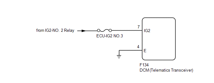
WIRING DIAGRAM
CAUTION / NOTICE / HINT
NOTICE:
Inspect the fuses for circuits related to this system before performing the following procedure.
PROCEDURE
|
1. |
CHECK DTC OUTPUT |
(a) Clear the DTCs.
Click here
.gif)
(b) Recheck for DTCs and check if the same DTC is output again.
Click here
|
Result |
Proceed to |
|---|---|
|
B15C6 is not output. |
A |
|
B15C6 is output. |
B |
| A | .gif) |
USE SIMULATION METHOD TO CHECK |
|
.gif)
|
2. |
CHECK HARNESS AND CONNECTOR (DCM [TELEMATICS TRANSCEIVER] - BATTERY AND BODY GROUND) |
|
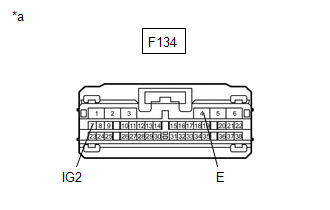
(a) Disconnect the DCM (Telematics Transceiver) connector. |
|
(b) Measure the resistance according to the value(s) in the table below.
Standard Resistance:
|
Tester Connection |
Condition |
Specified Condition |
|---|---|---|
|
F134-4 (E) - Body ground |
Always |
Below 1 Ω |
(c) Measure the voltage according to the value(s) in the table below.
Standard Voltage:
|
Tester Connection |
Switch Condition |
Specified Condition |
|---|---|---|
|
F134-7 (IG2) - Body ground |
Ignition switch ON |
11 to 14 V |
| NG | |
REPAIR OR REPLACE HARNESS OR CONNECTOR |
|
|
3. |
REPLACE DCM (TELEMATICS TRANSCEIVER) |
(a) Replace the DCM (Telematics Transceiver).
Click here
NOTICE:
- The ignition switch must be off.
- Do not exchange the DCM (Telematics Transceiver) with one from another vehicle.
| NEXT | |
PERFORM DCM ACTIVATION |
 Manual Button Malfunction (B15C5)
DESCRIPTION
This DTC is set when the DCM (Telematics Transceiver) detects an open or short
circuit in the manual (SOS) switch.
DTC No.
Detection Item
DTC Detection ...
 Telephone Microphone Error (B1572)
DESCRIPTION
This DTC is set when the DCM (Telematics Transceiver) detects a malfunction in
the telephone microphone assembly circuit.
DTC No.
Detection Item
DTC De ...
Other materials:
Toyota CH-R Service Manual > Pre-collision System: Skid Control Buzzer Circuit (C1A4A)
DESCRIPTION
The millimeter wave radar sensor assembly is connected to the forward recognition
camera via CAN communication.
The millimeter wave radar sensor assembly operates the pre-collision alarm by
sending a buzzer request signal to the pre-collision city buzzer.
If the millimeter wave ra ...
Toyota CH-R Service Manual > Clock System: How To Proceed With Troubleshooting
PROCEDURE
1.
VEHICLE BROUGHT TO WORKSHOP
NEXT
2.
CUSTOMER PROBLEM ANALYSIS
NEXT
3.
...
Toyota C-HR (AX20) 2023-2026 Owner's Manual
Toyota CH-R Owners Manual
- For safety and security
- Instrument cluster
- Operation of each component
- Driving
- Interior features
- Maintenance and care
- When trouble arises
- Vehicle specifications
- For owners
Toyota CH-R Service Manual
- Introduction
- Maintenance
- Audio / Video
- Cellular Communication
- Navigation / Multi Info Display
- Park Assist / Monitoring
- Brake (front)
- Brake (rear)
- Brake Control / Dynamic Control Systems
- Brake System (other)
- Parking Brake
- Axle And Differential
- Drive Shaft / Propeller Shaft
- K114 Cvt
- 3zr-fae Battery / Charging
- Networking
- Power Distribution
- Power Assist Systems
- Steering Column
- Steering Gear / Linkage
- Alignment / Handling Diagnosis
- Front Suspension
- Rear Suspension
- Tire / Wheel
- Tire Pressure Monitoring
- Door / Hatch
- Exterior Panels / Trim
- Horn
- Lighting (ext)
- Mirror (ext)
- Window / Glass
- Wiper / Washer
- Door Lock
- Heating / Air Conditioning
- Interior Panels / Trim
- Lighting (int)
- Meter / Gauge / Display
- Mirror (int)
- Power Outlets (int)
- Pre-collision
- Seat
- Seat Belt
- Supplemental Restraint Systems
- Theft Deterrent / Keyless Entry

0.0086