Toyota CH-R Service Manual: Manual Button Malfunction (B15C5)
DESCRIPTION
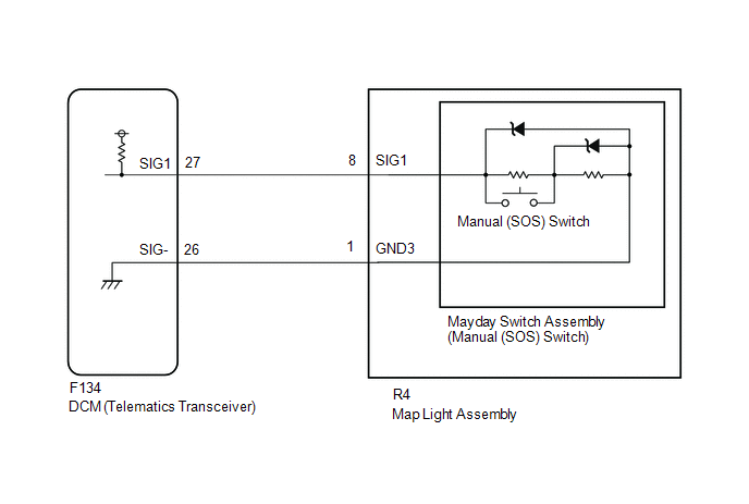
This DTC is set when the DCM (Telematics Transceiver) detects an open or short circuit in the manual (SOS) switch.
|
DTC No. |
Detection Item |
DTC Detection Condition |
Trouble Area |
|---|---|---|---|
|
B15C5 |
Manual Button Malfunction |
Open or short circuit in manual (SOS) switch is detected. |
|
WIRING DIAGRAM
CAUTION / NOTICE / HINT
HINT:
Before performing this diagnostic procedure, make sure to perform Health Check and confirm that the DCM/VIN registration information is correct.
Click here
.gif)
PROCEDURE
|
1. |
CHECK DTC |
(a) Turn the ignition switch off.
(b) Connect the Techstream to the DLC3.
(c) Turn the ignition switch ON and wait for 10 seconds.
(d) Turn the Techstream on.
(e) Clear the DTCs.
Body Electrical > Telematics > Clear DTCs(f) Recheck for DTCs.
Body Electrical > Telematics > Trouble Codes|
Result |
Proceed to |
|---|---|
|
DTC B1570, B1571 and B15C5 are output |
A |
|
DTC B15C5 is output (DTC B1570 and B1571 are not output) |
B |
| B | .gif) |
GO TO STEP 6 |
|
.gif)
|
2. |
INSPECT MAP LIGHT ASSEMBLY |
|
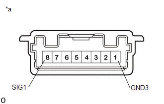
(a) Disconnect the R4 map light assembly connector. |
|
(b) Measure the resistance according to the value(s) in the table below.
Standard Resistance:
|
Tester Connection |
Switch Condition |
Specified Condition |
|---|---|---|
|
8 (SIG1) - 1 (GND3) |
Manual (SOS) switch not pressed |
392 to 432 Ω |
|
8 (SIG1) - 1 (GND3) |
Manual (SOS) switch pressed |
78 to 86 Ω |
| NG | |
GO TO STEP 5 |
|
|
3. |
CHECK HARNESS AND CONNECTOR (DCM (TELEMATICS TRANSCEIVER) - MAP LIGHT ASSEMBLY) |
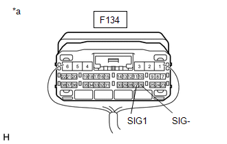
(a) Disconnect the F134 DCM (Telematics Transceiver) connector.
(b) Disconnect the R4 map light assembly connector.
(c) Measure the resistance according to the value(s) in the table below.
Standard Resistance:
|
Tester Connection |
Condition |
Specified Condition |
|---|---|---|
|
F134-26 (SIG-) - R4-1 (GND3) |
Always |
Below 1 Ω |
|
F134-26 (SIG-) or R4-1 (GND3) - Body ground |
Always |
10 kΩ or higher |
|
F134-27 (SIG1) - R4-8 (SIG1) |
Always |
Below 1 Ω |
|
F134-27 (SIG1) or R4-8 (SIG1) - Body ground |
Always |
10 kΩ or higher |
| NG | |
REPAIR OR REPLACE HARNESS OR CONNECTOR |
|
|
4. |
REPLACE DCM (TELEMATICS TRANSCEIVER) |
(a) Replace the DCM (Telematics Transceiver).
Click here
NOTICE:
- The ignition switch must be off.
- Do not swap the DCM (Telematics Transceiver) with one from another vehicle.
| NEXT | |
PERFORM DCM ACTIVATION |
|
5. |
INSPECT MAYDAY SWITCH ASSEMBLY (MANUAL (SOS) SWITCH) (RED INDICATOR) |
(a) Remove the mayday switch assembly (manual (SOS) switch).
Click here
(b) Inspect the mayday switch assembly (manual (SOS) switch).
Click here
| OK | |
REPLACE MAP LIGHT ASSEMBLY |
| NG | |
REPLACE MAYDAY SWITCH ASSEMBLY (MANUAL (SOS) SWITCH) |
|
6. |
READ VALUE USING TECHSTREAM (MANUAL (SOS) SWITCH OPERATION) |
(a) Turn the ignition switch off.
(b) Connect the Techstream to the DLC3.
(c) Turn the ignition switch ON and wait for 10 seconds.
(d) Turn the Techstream on.
(e) Enter the following menus: Body Electrical / Telematics / Data List.
(f) Check that the manual (SOS) switch condition observed on the Techstream changes according to manual (SOS) switch operation.
Body Electrical > Telematics > Data List|
Tester Display |
Measurement Item |
Range |
Normal Condition |
Diagnostic Note |
|---|---|---|---|---|
|
Emergency Switch |
Manual (SOS) switch |
OFF or ON |
OFF: Manual (SOS) switch not pressed ON: Manual (SOS) switch pressed* |
- |
|
Tester Display |
|---|
|
Emergency Switch |
- *: Pressing the manual (SOS) switch will connect to the call center.
|
Result |
Proceed to |
|---|---|
|
Techstream display changes when turning the manual (SOS) switch ON/OFF |
A |
|
Techstream display does not change when turning the manual (SOS) switch ON/OFF |
B |
| B | |
GO TO STEP 8 |
|
|
7. |
REPLACE DCM (TELEMATICS TRANSCEIVER) |
(a) Replace the DCM (Telematics Transceiver).
Click here
NOTICE:
- The ignition switch must be off.
- Do not swap the DCM (Telematics Transceiver) with one from another vehicle.
| NEXT | |
PERFORM DCM ACTIVATION |
|
8. |
INSPECT DCM (TELEMATICS TRANSCEIVER) (SIG1 VOLTAGE) |
|
(a) Remove the DCM (Telematics Transceiver) but do not disconnect the connectors. Click here
|
|
(b) Measure the voltage according to the value(s) in the table below.
Standard Voltage:
|
Tester Connection |
Switch Condition |
Specified Condition |
|---|---|---|
|
F134-27 (SIG1) - F134-26 (SIG-) |
Ignition switch ON manual (SOS) switch not pressed |
1.5 to 2.0 V |
| NG | |
GO TO STEP 10 |
|
|
9. |
REPLACE DCM (TELEMATICS TRANSCEIVER) |
(a) Replace the DCM (Telematics Transceiver).
Click here
NOTICE:
- The ignition switch must be off.
- Do not swap the DCM (Telematics Transceiver) with one from another vehicle.
| NEXT | |
PERFORM DCM ACTIVATION |
|
10. |
INSPECT MAP LIGHT ASSEMBLY |
|
(a) Disconnect the R4 map light assembly connector. |
|

(b) Measure the resistance according to the value(s) in the table below.
Standard Resistance:
|
Tester Connection |
Condition |
Specified Condition |
|---|---|---|
|
8 (SIG1) - 1 (GND3) |
Manual (SOS) switch not pressed |
392 to 432 Ω |
|
8 (SIG1) - 1 (GND3) |
Manual (SOS) switch pressed |
78 to 86 Ω |
| NG | |
GO TO STEP 13 |
|
|
11. |
CHECK HARNESS AND CONNECTOR (DCM (TELEMATICS TRANSCEIVER) - MAYDAY SWITCH ASSEMBLY (MANUAL (SOS) SWITCH)) |
(a) Disconnect the F134 DCM (Telematics Transceiver) connector.
(b) Disconnect the R4 map light assembly connector.
(c) Measure the resistance according to the value(s) in the table below.
Standard Resistance:
|
Tester Connection |
Condition |
Specified Condition |
|---|---|---|
|
F134-27 (SIG1) -R4-8 (SIG1) |
Always |
Below 1 Ω |
|
F134-27 (SIG1) or R4-8 (SIG1) - Body ground |
Always |
10 kΩ or higher |
| NG | |
REPAIR OR REPLACE HARNESS OR CONNECTOR |
|
|
12. |
REPLACE DCM (TELEMATICS TRANSCEIVER) |
(a) Replace the DCM (Telematics Transceiver).
Click here
NOTICE:
- The ignition switch must be off.
- Do not swap the DCM (Telematics Transceiver) with one from another vehicle.
| NEXT | |
PERFORM DCM ACTIVATION |
|
13. |
INSPECT MAYDAY SWITCH ASSEMBLY (MANUAL (SOS) SWITCH) (RED INDICATOR) |
(a) Remove the mayday switch assembly (manual (SOS) switch).
Click here
(b) Inspect the mayday switch assembly (manual (SOS) switch).
Click here
| OK | |
REPLACE MAP LIGHT ASSEMBLY |
| NG | |
REPLACE MAYDAY SWITCH ASSEMBLY (MANUAL (SOS) SWITCH) |
 Airbag Signal Malfunction/Not Input (B15C4)
DESCRIPTION
If the DCM (Telematics Transceiver) detects an error in communication between
the DCM (Telematics Transceiver) and the airbag sensor assembly as a result of the
DCM (Telematics Transc ...
 Ignition Switch Signal Malfunction (B15C6)
DESCRIPTION
If vehicle movement (10 km/h (6 mph) or more for 10 seconds) is detected based
on the location data sent from the radio receiver assembly even when the telematics
transceiver detects ...
Other materials:
Toyota CH-R Service Manual > Side Airbag Sensor(for Front Door): On-vehicle Inspection
ON-VEHICLE INSPECTION
CAUTION / NOTICE / HINT
CAUTION:
Be sure to correctly follow the removal and installation procedures for the door
side airbag sensors.
PROCEDURE
1. INSPECT DOOR SIDE AIRBAG SENSOR (for Vehicle not Involved in Collision)
(a) Perform a diagnostic system check.
Click here ...
Toyota CH-R Service Manual > Main Body Ecu: Components
COMPONENTS
ILLUSTRATION
*A
except Cold Area Specification Vehicles
*B
for Cold Area Specification Vehicles
*1
INSTRUMENT PANEL JUNCTION BLOCK ASSEMBLY WITH MAIN BODY ECU
*2
NO. 3 INSTRUMENT PANEL TO COW ...
Toyota C-HR (AX20) 2023-2026 Owner's Manual
Toyota CH-R Owners Manual
- For safety and security
- Instrument cluster
- Operation of each component
- Driving
- Interior features
- Maintenance and care
- When trouble arises
- Vehicle specifications
- For owners
Toyota CH-R Service Manual
- Introduction
- Maintenance
- Audio / Video
- Cellular Communication
- Navigation / Multi Info Display
- Park Assist / Monitoring
- Brake (front)
- Brake (rear)
- Brake Control / Dynamic Control Systems
- Brake System (other)
- Parking Brake
- Axle And Differential
- Drive Shaft / Propeller Shaft
- K114 Cvt
- 3zr-fae Battery / Charging
- Networking
- Power Distribution
- Power Assist Systems
- Steering Column
- Steering Gear / Linkage
- Alignment / Handling Diagnosis
- Front Suspension
- Rear Suspension
- Tire / Wheel
- Tire Pressure Monitoring
- Door / Hatch
- Exterior Panels / Trim
- Horn
- Lighting (ext)
- Mirror (ext)
- Window / Glass
- Wiper / Washer
- Door Lock
- Heating / Air Conditioning
- Interior Panels / Trim
- Lighting (int)
- Meter / Gauge / Display
- Mirror (int)
- Power Outlets (int)
- Pre-collision
- Seat
- Seat Belt
- Supplemental Restraint Systems
- Theft Deterrent / Keyless Entry

0.01