Toyota CH-R Service Manual: Precaution
PRECAUTION
HINT:
In the airbag system, the parts listed below are collectively referred to as the airbag sensors.- Airbag sensor assembly
- Front airbag sensor
- Door side airbag sensors
- No. 1 side airbag sensor
- Floor side airbag sensor
- No. 2 side airbag sensor
- Horn button assembly
- Lower No. 1 instrument panel airbag assembly
- Instrument panel passenger without door airbag assembly
- Curtain shield airbag assemblies
- Front seat airbag assemblies
- Front seat outer belt assemblies
- Rear seat 3 point type outer belt assemblies*
- Rear seat airbag assemblies*
- Front seat cushion airbag assembly RH*
- *: w/ Occupant Classification System
PRECAUTION FOR HANDLING SRS SYSTEM
(a) Failure to carry out service operations in the correct sequence could cause the SRS to unexpectedly deploy during servicing, possibly leading to a serious accident. Furthermore, if a mistake is made when servicing the SRS, it is possible that the SRS may fail to operate when required. Before servicing (including removal or installation of parts, inspection or replacement), be sure to read the following precautions carefully, then follow the procedures exactly as indicated in the repair manual.
PRECAUTION FOR DISCONNECTING CABLE FROM NEGATIVE BATTERY TERMINAL
(a) As SRS malfunctions are difficult to confirm, Diagnostic Trouble Codes (DTCs) become the most important source of information when troubleshooting. When troubleshooting the SRS, always check for DTCs before disconnecting the cable from the negative (-) battery terminal.
NOTICE:
After turning the ignition switch off, waiting time may be required before disconnecting the cable from the negative (-) battery terminal. Therefore, make sure to read the disconnecting the cable from the negative (-) battery terminal notices before proceeding with work.
Click here .gif)
(b) When the cable is disconnected from the negative (-) battery terminal, the memory of various systems will be cleared. Because of this, be sure to make a record of the contents memorized in each system before starting work. When work is finished, adjust each system to its previous state.
GENERAL PRECAUTION
(a) Use a voltmeter/ohmmeter with high impedance (minimum = 10 kΩ) for troubleshooting electrical circuits.
(b) Information labels are attached to the SRS parts. Follow the instructions on the labels.
(c) Never disassemble or attempt to repair any of the SRS parts.
(d) If any of the SRS parts are dropped, or if any cracks, dents or other defects are found, replace them with new parts.
(e) Never use SRS parts from another vehicle. When replacing parts, use new parts.
(f) Do not expose any of the SRS parts directly to high temperatures or flames.
(g) If the vehicle has been involved in a minor collision where the SRS did not deploy, the SRS parts should be inspected before further use of the vehicle.
(h) Do not apply grease, detergent, oil or water to the SRS parts. If applied, immediately wipe it off with a dry cloth.
(i) When deploying or storing the SRS parts, avoid places with a high temperature (ambient temperature of 93°C (199°F) or higher for an airbag and 80°C (176°F) or higher for a pretensioner) and high humidity, and keep them away from electrical noise.
(j) Do not stack or place anything on top of the SRS parts.
(k) When disposing of the vehicle or an SRS part by itself, deploy the SRS parts using SST before disposal. Deploy the SRS parts in a safe place away from electrical noise.
HINT:
- Horn button assembly
Click here
- Lower No. 1 instrument panel airbag assembly
Click here
- Instrument panel passenger without door airbag assembly
Click here
- Curtain shield airbag assemblies
Click here
- Front seat airbag assemblies
Click here
- Front seat cushion airbag assembly RH*
- Front seat outer belt assemblies
Click here
- Rear seat 3 point type outer belt assemblies*Rear seat airbag assemblies*
- *: w/ Occupant Classification System
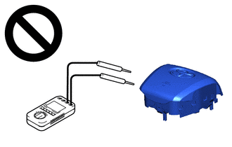
(l) Never measure the resistance of the SRS parts.
CAUTION:
Never measure the resistance of the SRS parts because current from the tester may cause the SRS parts to deploy.
PRECAUTION FOR DISPOSAL OF SRS PARTS (NOT DEPLOYED)
(a) Before performing pre-disposal deployment of any SRS parts, review and closely follow all applicable environmental and hazardous material regulations. Pre-disposal deployment may be considered hazardous material treatment.
(b) Never dispose of any SRS parts that have not been deployed.
(c) Deploy the SRS parts outdoors in a safe and level place where it will not disturb nearby residents.
(d) As the SRS parts produce a loud sound when deployed, be sure to inform nearby residents before deployment.
(e) When deploying the SRS parts, always use the specified SST and keep people at least 10 m (32.8 ft.) away.
(f) The SRS parts may be accidentally deployed by static electricity. To prevent this, be sure to touch a metal surface with your bare hands to discharge static electricity before handling the SRS parts.
(g) Do not face the deployment side of an airbag down when deploying an airbag.
PRECAUTION FOR DISPOSAL OF SRS PARTS (DEPLOYED)
(a) As the SRS parts are very hot after being deployed, allow at least 30 minutes for them to cool down sufficiently before disposal.
(b) Do not apply water, etc. to any deployed SRS parts.
(c) Use gloves and safety glasses when handling any deployed SRS parts.
(d) Seal the deployed SRS parts in a thick clear plastic bag when disposing of them.
(e) Always wash your hands with water after disposing of deployed SRS parts.
PRECAUTION FOR HORN BUTTON ASSEMBLY, LOWER NO. 1 INSTRUMENT PANEL AIRBAG ASSEMBLY, INSTRUMENT PANEL PASSENGER WITHOUT DOOR AIRBAG ASSEMBLY, CURTAIN SHIELD AIRBAG ASSEMBLY REAR SEAT AIRBAG ASSEMBLY, FRONT SEAT CUSHION AIRBAG ASSEMBLY RH AND FRONT SEAT AIRBAG ASSEMBLY
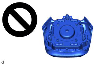
(a) Keep the deployment side of an airbag facing upward even when the airbag is temporarily removed during service.
CAUTION:
Always place a removed or a new airbag with the deployment side facing upward. Placing the airbag with the deployment side facing downward could cause a serious accident if the airbag deploys.
PRECAUTION FOR FRONT SEAT OUTER BELT ASSEMBLY (PRETENSIONER) AND REAR SEAT 3 POINT TYPE OUTER BELT ASSEMBLY (PRETENSIONER)
(a) Do not touch the area around the retractor even when the front seat outer belt assembly is temporarily removed during service.
CAUTION:
If the pretensioner unexpectedly deploys and the front seat outer belt assembly is retracted during an operation, it could cause a serious accident.
.png)
PRECAUTION FOR SPIRAL CABLE WITH SENSOR SUB-ASSEMBLY
(a) Do not replace the spiral cable with sensor sub-assembly with the battery connected and the ignition switch ON.
(b) Do not rotate the spiral cable with sensor sub-assembly without the steering wheel assembly installed, with the battery connected and the ignition switch ON.
(c) Ensure that the steering wheel assembly is installed and aligned straight when inspecting the steering sensor.
(d) When rotating the spiral cable with sensor sub-assembly, make sure to push on the interlock to release the interlock mechanism.
(e) Be sure that the spiral cable with sensor sub-assembly is in the neutral position during installation and when removing and installing the steering wheel assembly.
Click here
CAUTION:
If the steering wheel assembly is turned without the spiral cable with sensor sub-assembly installed in the neutral position, the cable may break.
PRECAUTION FOR AIRBAG SENSORS
(a) Perform a diagnostic system check.
Click here
(b) When the SRS parts are deployed (including when only an airbag or pretensioner is deployed) due to a collision, be sure to replace all sensors in the damaged areas (anywhere in need of repair) and the airbag sensor assembly.
(c) Visually check the airbag sensors in undamaged areas for defects.
(1) The defects are as follows:
- Cracks in the sensor housing
- Dents in the sensor housing
- Chips in the sensor housing
- Cracks or other damage to the connector
- Damage to the serial number (except door side airbag sensor)
OK:
No defects are found.
If any defects are found or an airbag sensor has detected a major collision, replace the airbag sensor with a new one.
PRECAUTION WHEN REPLACING AIRBAG SENSOR ASSEMBLY
(a) When the airbag sensor assembly is replaced, perform zero point learning for the yaw rate and acceleration sensor.
Click here
PRECAUTION FOR DOOR SIDE AIRBAG SENSOR
(a) Do not make any modifications to the front door that may change the inner pressure of the front door.
(b) Do not allow any foreign matter to enter the door side airbag sensor as it may affect the pressure detection performance of the sensor.
(c) When painting the front door, remove or apply protective tape to the door side airbag sensor to prevent paint from attaching to it.
(d) Make sure that the parts which maintain the sealing performance of the front door are securely installed. If the sealing performance of the front door decreases, the pressure detection performance of the door side airbag sensor may be affected. Repair or replace parts as necessary.
PRECAUTION FOR WIRE HARNESS AND CONNECTOR
(a) All wire harnesses except unexposed harnesses in the engine compartment are colored yellow.
(b) As special connectors are used, be careful when handling them.
WHEN SERVICING DAMAGED VEHICLE
(a) Before using an electric welder on the vehicle, remove any SRS parts around the area being repaired.
CAUTION:
Make sure to remove any SRS parts as necessary to prevent them from accidentally deploying.
(b) Before repairs, remove the airbag sensor assemblies if impacts are likely to be applied to the sensor during repairs.
(c) Never expose an airbag sensor directly to high temperatures.
(d) As the SRS parts are very hot after being deployed, ensure that all wire harnesses and connectors around deployed SRS parts are not damaged.
CONDITIONS WHEN INSPECTION OF SRS PARTS IS NECESSARY
(a) When the vehicle is damaged in a collision, even if the SRS parts are not deployed.
(b) When SRS system DTCs are output.
IGNITION SWITCH EXPRESSIONS
(a) The type of ignition switch used on this model differs according to the specification of the vehicle. The expressions listed in the table below are used in this section.
|
Expression |
Ignition Switch (Position) |
Engine Switch (Condition) |
|---|---|---|
|
Ignition Switch off |
LOCK |
Off (Lock) |
|
Ignition Switch ACC |
ACC |
On (ACC) |
|
Ignition Switch ON |
ON |
On (IG) |
|
Engine Start |
START |
On (Start) |
PRECAUTION WHEN REPLACING COMBINATION METER ASSEMBLY
(a) When replacing the combination meter assembly, always replace it with a new one. If a combination meter assembly which was installed to another vehicle is used, the information stored in it will not match the information from the vehicle and a DTC may be stored.
 Airbag System
...
 Parts Location
PARTS LOCATION
ILLUSTRATION
*1
FRONT AIRBAG SENSOR LH
*2
FRONT AIRBAG SENSOR RH
*3
DOOR SIDE AIRBAG SENSOR LH
*4
...
Other materials:
Toyota CH-R Service Manual > Brake Control / Dynamic Control Systems: Steering Angle Sensor
Components
COMPONENTS
ILLUSTRATION
*1
SPIRAL CABLE SUB-ASSEMBLY
*2
STEERING SENSOR
Removal
REMOVAL
CAUTION / NOTICE / HINT
The necessary procedures (adjustment, calibration, initialization, or registration)
that must be performed af ...
Toyota CH-R Service Manual > Smart Key System(for Entry Function): New Key cannot be Registered
DESCRIPTION
If a new electrical key transmitter sub-assembly could not be registered, wave
interference or a malfunction of the certification ECU (smart key ECU assembly),
electrical key transmitter sub-assembly, ID code box (immobiliser code ECU), steering
lock ECU (steering lock actuator or ...
Toyota C-HR (AX20) 2023-2026 Owner's Manual
Toyota CH-R Owners Manual
- For safety and security
- Instrument cluster
- Operation of each component
- Driving
- Interior features
- Maintenance and care
- When trouble arises
- Vehicle specifications
- For owners
Toyota CH-R Service Manual
- Introduction
- Maintenance
- Audio / Video
- Cellular Communication
- Navigation / Multi Info Display
- Park Assist / Monitoring
- Brake (front)
- Brake (rear)
- Brake Control / Dynamic Control Systems
- Brake System (other)
- Parking Brake
- Axle And Differential
- Drive Shaft / Propeller Shaft
- K114 Cvt
- 3zr-fae Battery / Charging
- Networking
- Power Distribution
- Power Assist Systems
- Steering Column
- Steering Gear / Linkage
- Alignment / Handling Diagnosis
- Front Suspension
- Rear Suspension
- Tire / Wheel
- Tire Pressure Monitoring
- Door / Hatch
- Exterior Panels / Trim
- Horn
- Lighting (ext)
- Mirror (ext)
- Window / Glass
- Wiper / Washer
- Door Lock
- Heating / Air Conditioning
- Interior Panels / Trim
- Lighting (int)
- Meter / Gauge / Display
- Mirror (int)
- Power Outlets (int)
- Pre-collision
- Seat
- Seat Belt
- Supplemental Restraint Systems
- Theft Deterrent / Keyless Entry

0.0084