Toyota CH-R Service Manual: Parts Location
PARTS LOCATION
ILLUSTRATION
|
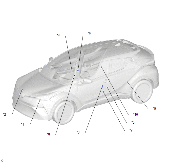
*1 |
FRONT AIRBAG SENSOR LH |
*2 |
FRONT AIRBAG SENSOR RH |
|
*3 |
DOOR SIDE AIRBAG SENSOR LH |
*4 |
DOOR SIDE AIRBAG SENSOR RH |
|
*5 |
NO. 1 SIDE AIRBAG SENSOR LH |
*6 |
NO. 1 SIDE AIRBAG SENSOR RH |
|
*7 |
FLOOR SIDE AIRBAG SENSOR LH |
*8 |
FLOOR SIDE AIRBAG SENSOR RH |
|
*9 |
NO. 2 SIDE AIRBAG SENSOR LH |
*10 |
NO. 2 SIDE AIRBAG SENSOR RH |
ILLUSTRATION
|
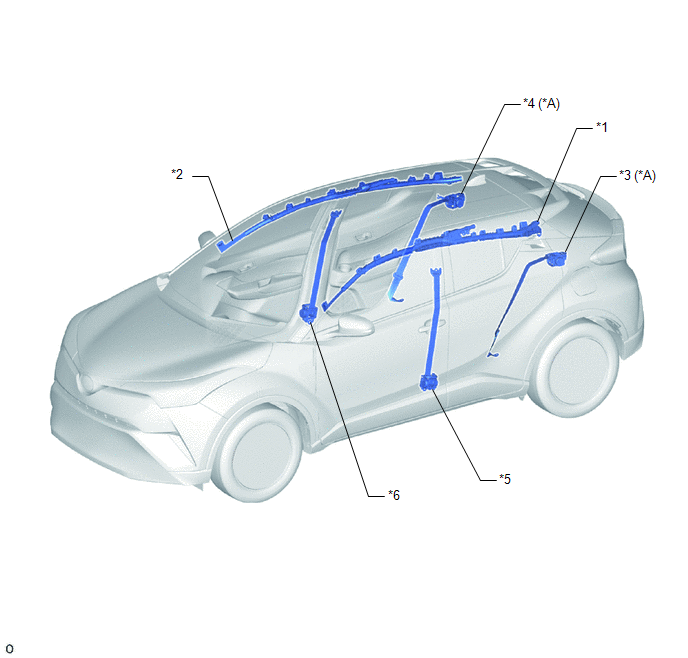
*A |
w/ Occupant Classification System |
- |
- |
|
*1 |
CURTAIN SHIELD AIRBAG ASSEMBLY LH |
*2 |
CURTAIN SHIELD AIRBAG ASSEMBLY RH |
|
*3 |
REAR SEAT 3 POINT TYPE OUTER BELT ASSEMBLY LH |
*4 |
REAR SEAT 3 POINT TYPE OUTER BELT ASSEMBLY RH |
|
*5 |
FRONT SEAT OUTER BELT ASSEMBLY LH |
*6 |
FRONT SEAT OUTER BELT ASSEMBLY RH |
ILLUSTRATION
|
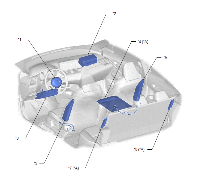
*A |
w/ Occupant Classification System |
- |
- |
|
*1 |
HORN BUTTON ASSEMBLY |
*2 |
INSTRUMENT PANEL PASSENGER WITHOUT DOOR AIRBAG ASSEMBLY |
|
*3 |
LOWER NO. 1 INSTRUMENT PANEL AIRBAG ASSEMBLY |
*4 |
FRONT SEAT CUSHION AIRBAG ASSEMBLY RH |
|
*5 |
FRONT SEAT AIRBAG ASSEMBLY LH |
*6 |
FRONT SEAT AIRBAG ASSEMBLY RH |
|
*7 |
REAR SEAT AIRBAG ASSEMBLY LH |
*8 |
REAR SEAT AIRBAG ASSEMBLY RH |
ILLUSTRATION
|
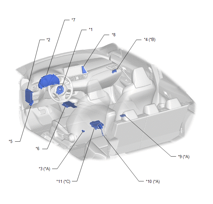
*A |
w/ Occupant Classification System |
*B |
w/o Occupant Classification System |
|
*C |
w/ Safety Connect System |
- |
- |
|
*1 |
SPIRAL CABLE WITH SENSOR SUB-ASSEMBLY |
*2 |
INSTRUMENT PANEL JUNCTION BLOCK ASSEMBLY - A/BAG-IG2 FUSE - ECU-DCC NO. 2 FUSE |
|
*3 |
SEAT POSITION AIRBAG SENSOR |
*4 |
AIRBAG CUT OFF SWITCH CYLINDER SUB-ASSEMBLY |
|
*5 |
DLC3 |
*6 |
AIRBAG SENSOR ASSEMBLY |
|
*7 |
COMBINATION METER ASSEMBLY - SRS WARNING LIGHT |
*8 |
CLOCK ASSEMBLY - PASSENGER AIRBAG ON/OFF INDICATOR |
|
*9 |
OCCUPANT DETECTION ECU |
*10 |
FRONT SEAT INNER BELT ASSEMBLY LH (SEAT BELT BUCKLE SWITCH LH) |
|
*11 |
DCM (TELEMATICS TRANSCEIVER) |
- |
- |
 Precaution
PRECAUTION
HINT:
In the airbag system, the parts listed below are collectively referred to as
the airbag sensors.
Airbag sensor assembly
Front airbag sensor
Door side airbag sen ...
 System Diagram
SYSTEM DIAGRAM
Communication Table
Transmitting ECU
(Transmitter)
Receiving ECU
Signal
Communication Method
Airbag Sensor Assem ...
Other materials:
Toyota CH-R Service Manual > Automatic High Beam System: Lost Communication with Front Camera Module (U023A)
DESCRIPTION
This DTC is stored when the CAN communication system is malfunctioning.
DTC No.
Detection Item
DTC Detection Condition
Trouble Area
U023A
Lost Communication with Front Camera Module
Lost communication wi ...
Toyota CH-R Service Manual > Fog Light Assembly: Installation
INSTALLATION
CAUTION / NOTICE / HINT
HINT:
Use the same procedure for the RH side and LH side.
The following procedure is for the LH side.
PROCEDURE
1. INSTALL FOG LIGHT ASSEMBLY
(a) Engage the guide to install the fog light assembly.
...
Toyota C-HR (AX20) 2023-2026 Owner's Manual
Toyota CH-R Owners Manual
- For safety and security
- Instrument cluster
- Operation of each component
- Driving
- Interior features
- Maintenance and care
- When trouble arises
- Vehicle specifications
- For owners
Toyota CH-R Service Manual
- Introduction
- Maintenance
- Audio / Video
- Cellular Communication
- Navigation / Multi Info Display
- Park Assist / Monitoring
- Brake (front)
- Brake (rear)
- Brake Control / Dynamic Control Systems
- Brake System (other)
- Parking Brake
- Axle And Differential
- Drive Shaft / Propeller Shaft
- K114 Cvt
- 3zr-fae Battery / Charging
- Networking
- Power Distribution
- Power Assist Systems
- Steering Column
- Steering Gear / Linkage
- Alignment / Handling Diagnosis
- Front Suspension
- Rear Suspension
- Tire / Wheel
- Tire Pressure Monitoring
- Door / Hatch
- Exterior Panels / Trim
- Horn
- Lighting (ext)
- Mirror (ext)
- Window / Glass
- Wiper / Washer
- Door Lock
- Heating / Air Conditioning
- Interior Panels / Trim
- Lighting (int)
- Meter / Gauge / Display
- Mirror (int)
- Power Outlets (int)
- Pre-collision
- Seat
- Seat Belt
- Supplemental Restraint Systems
- Theft Deterrent / Keyless Entry

0.0081