Toyota CH-R Service Manual: Installation
INSTALLATION
PROCEDURE
1. INSTALL RADIO SETTING CONDENSER
|
(a) Engage the claw to install a new terminal cover to the wire harness. NOTICE:
|
|
|
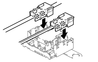
(b) Engage the 6 claws to install the 2 new terminal covers with wire harness to a new radio setting condenser. NOTICE:
|
|
|
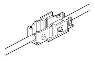
(c) Insert the cover as shown in the illustration and engage the claw. |
|
|
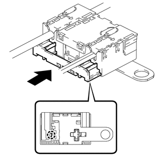
(d) Engage the clamp to temporarily install the radio setting condenser with wire harness. |
|
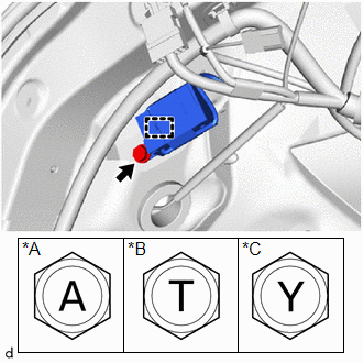
(e) Install the radio setting condenser with the bolt.
Torque:
for Type A :
10.5 N·m {107 kgf·cm, 8 ft·lbf}
for Type B :
10 N·m {102 kgf·cm, 7 ft·lbf}
for Type C :
10 N·m {102 kgf·cm, 7 ft·lbf}
2. INSTALL DECK TRIM SIDE PANEL ASSEMBLY LH
Click here
.gif)
3. INSTALL NO. 1 LUGGAGE COMPARTMENT LIGHT ASSEMBLY
Click here
4. INSTALL DECK TRIM REAR COVER
Click here
5. INSTALL REAR SEAT SIDE GARNISH LH (w/o Rear Seat Side Airbag)
Click here
6. INSTALL REAR SEAT SIDE GARNISH LH (w/ Rear Seat Side Airbag)
Click here
7. INSTALL REAR PILLAR COVER LH (w/ Rear Seat Side Airbag)
Click here
8. INSTALL REAR SEATBACK HINGE SUB-ASSEMBLY LH
Click here
9. CONNECT REAR DOOR OPENING TRIM WEATHERSTRIP LH
Click here
10. INSTALL REAR DOOR SCUFF PLATE LH (w/o Rear Seat Side Airbag)
Click here
11. INSTALL REAR DOOR SCUFF PLATE LH (w/ Rear Seat Side Airbag)
Click here
12. INSTALL BENCH TYPE REAR SEAT CUSHION ASSEMBLY
Click here
13. INSTALL DECK FLOOR BOX LH
Click here
14. INSTALL DECK FLOOR BOX RH
Click here
15. INSTALL SPARE WHEEL CUSHION
Click here
16. INSTALL DECK BOARD ASSEMBLY
Click here
17. INSTALL TONNEAU COVER ASSEMBLY (w/ Tonneau Cover)
Click here
18. INSTALL PACKAGE TRAY TRIM PANEL ASSEMBLY (w/ Package Tray Trim)
Click here
 Removal
REMOVAL
PROCEDURE
1. REMOVE PACKAGE TRAY TRIM PANEL ASSEMBLY (w/ Package Tray Trim)
Click here
2. REMOVE TONNEAU COVER ASSEMBLY (w/ Tonneau Cover)
Click here
3. REMOVE DECK BOARD ASSEMBL ...

Other materials:
Toyota CH-R Service Manual > Maintenance: Back-up Light Bulb
Components
COMPONENTS
ILLUSTRATION
*1
BACK DOOR SERVICE HOLE COVER LH
*2
BACK UP LIGHT BULB
*3
BACK UP LIGHT SOCKET AND WIRE
-
-
Removal
REMOVAL
CAUTION / NOTICE / HINT
HINT:
...
Toyota CH-R Service Manual > Front Seat Assembly: Installation
INSTALLATION
CAUTION / NOTICE / HINT
CAUTION:
Be sure to read Precaution thoroughly before servicing.
Click here
Wear protective gloves. Sharp areas on the parts may injure your hands.
HINT:
Use the same procedure for the driver side and front passen ...
Toyota C-HR (AX20) 2023-2026 Owner's Manual
Toyota CH-R Owners Manual
- For safety and security
- Instrument cluster
- Operation of each component
- Driving
- Interior features
- Maintenance and care
- When trouble arises
- Vehicle specifications
- For owners
Toyota CH-R Service Manual
- Introduction
- Maintenance
- Audio / Video
- Cellular Communication
- Navigation / Multi Info Display
- Park Assist / Monitoring
- Brake (front)
- Brake (rear)
- Brake Control / Dynamic Control Systems
- Brake System (other)
- Parking Brake
- Axle And Differential
- Drive Shaft / Propeller Shaft
- K114 Cvt
- 3zr-fae Battery / Charging
- Networking
- Power Distribution
- Power Assist Systems
- Steering Column
- Steering Gear / Linkage
- Alignment / Handling Diagnosis
- Front Suspension
- Rear Suspension
- Tire / Wheel
- Tire Pressure Monitoring
- Door / Hatch
- Exterior Panels / Trim
- Horn
- Lighting (ext)
- Mirror (ext)
- Window / Glass
- Wiper / Washer
- Door Lock
- Heating / Air Conditioning
- Interior Panels / Trim
- Lighting (int)
- Meter / Gauge / Display
- Mirror (int)
- Power Outlets (int)
- Pre-collision
- Seat
- Seat Belt
- Supplemental Restraint Systems
- Theft Deterrent / Keyless Entry

0.013