Toyota CH-R Service Manual: Removal
REMOVAL
PROCEDURE
1. REMOVE PACKAGE TRAY TRIM PANEL ASSEMBLY (w/ Package Tray Trim)
Click here
.gif)
2. REMOVE TONNEAU COVER ASSEMBLY (w/ Tonneau Cover)
Click here
3. REMOVE DECK BOARD ASSEMBLY
Click here
4. REMOVE SPARE WHEEL CUSHION
Click here
5. REMOVE DECK FLOOR BOX LH
Click here
6. REMOVE DECK FLOOR BOX RH
Click here
7. REMOVE BENCH TYPE REAR SEAT CUSHION ASSEMBLY
Click here
8. REMOVE REAR DOOR SCUFF PLATE LH (w/o Rear Seat Side Airbag)
Click here
9. REMOVE REAR DOOR SCUFF PLATE LH (w/ Rear Seat Side Airbag)
Click here
10. DISCONNECT REAR DOOR OPENING TRIM WEATHERSTRIP LH
Click here
11. REMOVE REAR SEATBACK HINGE SUB-ASSEMBLY LH
Click here
12. REMOVE REAR SEAT SIDE GARNISH LH (w/o Rear Seat Side Airbag)
Click here
13. REMOVE REAR PILLAR COVER LH (w/ Rear Seat Side Airbag)
Click here
14. REMOVE REAR SEAT SIDE GARNISH LH (w/ Rear Seat Side Airbag)
Click here
15. REMOVE DECK TRIM REAR COVER
Click here
16. REMOVE NO. 1 LUGGAGE COMPARTMENT LIGHT ASSEMBLY
Click here
17. REMOVE DECK TRIM SIDE PANEL ASSEMBLY LH
Click here
18. REMOVE RADIO SETTING CONDENSER
NOTICE:
When the terminal cover is removed, the radio setting condenser must be replaced because the terminal cover and radio setting condenser are supplied as a set.
|
(a) Remove the bolt. |
|

(b) Using a clip remover, disengage the clamp to disconnect the radio setting condenser with wire harness from the vehicle body.
|
(c) Disengage the claw to pull out the cover as shown in the illustration. |
|
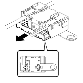
|
(d) Using a screwdriver, disengage the 6 claws to remove the 2 terminal covers with wire harness from the radio setting condenser. |
|
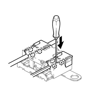
|
(e) Using a screwdriver, bend back and break off the claw as shown in the illustration. |
|
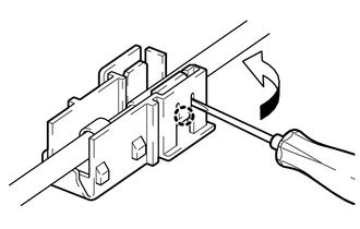
(f) Remove the terminal cover from the wire harness.
NOTICE:
- Make sure to hold the crimping side of the terminal when disconnecting the wire harness from the terminal cover.
- Make sure not to bend the exposed wire when disconnecting the wire harness from the terminal cover.
- Check for deformation of the terminal after the wire harness has been removed from the terminal cover.
 On-vehicle Inspection
ON-VEHICLE INSPECTION
PROCEDURE
1. INSPECT RADIO SETTING CONDENSER
(a) With the radio setting condenser installed, check that there is no looseness
or other abnormalities.
(b) Measure ...
 Installation
INSTALLATION
PROCEDURE
1. INSTALL RADIO SETTING CONDENSER
(a) Engage the claw to install a new terminal cover to the wire harness.
NOTICE:
Make sure to hold the crimpi ...
Other materials:
Toyota CH-R Owners Manual > Using the air conditioning system and defogger: Seat heaters
Seat heaters heat the front seats.
WARNING
Care should be taken to prevent injury if anyone in the following categories
comes in contact with the seats when the heater is on:
Babies, small children, the elderly, the sick and the physically
challenged
Persons with sensitive sk ...
Toyota CH-R Service Manual > Audio And Visual System(for Radio And Display Type): Parts Location
PARTS LOCATION
ILLUSTRATION
*1
MAP LIGHT ASSEMBLY (TELEPHONE MICROPHONE ASSEMBLY)
*2
SKID CONTROL ECU (BRAKE ACTUATOR ASSEMBLY)
ILLUSTRATION
*1
FRONT NO. 1 SPEAKER ASSEMBLY LH
*2
FRONT NO. 1 SPEA ...
Toyota C-HR (AX20) 2023-2026 Owner's Manual
Toyota CH-R Owners Manual
- For safety and security
- Instrument cluster
- Operation of each component
- Driving
- Interior features
- Maintenance and care
- When trouble arises
- Vehicle specifications
- For owners
Toyota CH-R Service Manual
- Introduction
- Maintenance
- Audio / Video
- Cellular Communication
- Navigation / Multi Info Display
- Park Assist / Monitoring
- Brake (front)
- Brake (rear)
- Brake Control / Dynamic Control Systems
- Brake System (other)
- Parking Brake
- Axle And Differential
- Drive Shaft / Propeller Shaft
- K114 Cvt
- 3zr-fae Battery / Charging
- Networking
- Power Distribution
- Power Assist Systems
- Steering Column
- Steering Gear / Linkage
- Alignment / Handling Diagnosis
- Front Suspension
- Rear Suspension
- Tire / Wheel
- Tire Pressure Monitoring
- Door / Hatch
- Exterior Panels / Trim
- Horn
- Lighting (ext)
- Mirror (ext)
- Window / Glass
- Wiper / Washer
- Door Lock
- Heating / Air Conditioning
- Interior Panels / Trim
- Lighting (int)
- Meter / Gauge / Display
- Mirror (int)
- Power Outlets (int)
- Pre-collision
- Seat
- Seat Belt
- Supplemental Restraint Systems
- Theft Deterrent / Keyless Entry

0.0073