Toyota CH-R Service Manual: Satellite Radio Broadcast cannot be Received
CAUTION / NOTICE / HINT
NOTICE:
Some satellite radio broadcasts require payment. A contract must be made between a satellite radio company and the user. If the contract expires, it will not be possible to listen to the broadcast.
WIRING DIAGRAM
for TMMT Made
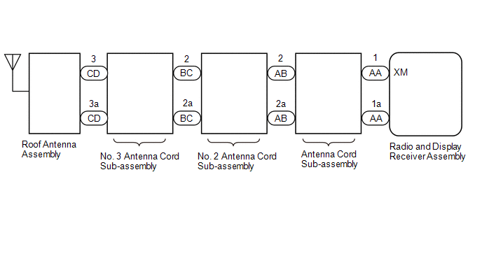
for TMC Made

PROCEDURE
|
1. |
CHECK SURROUNDINGS |
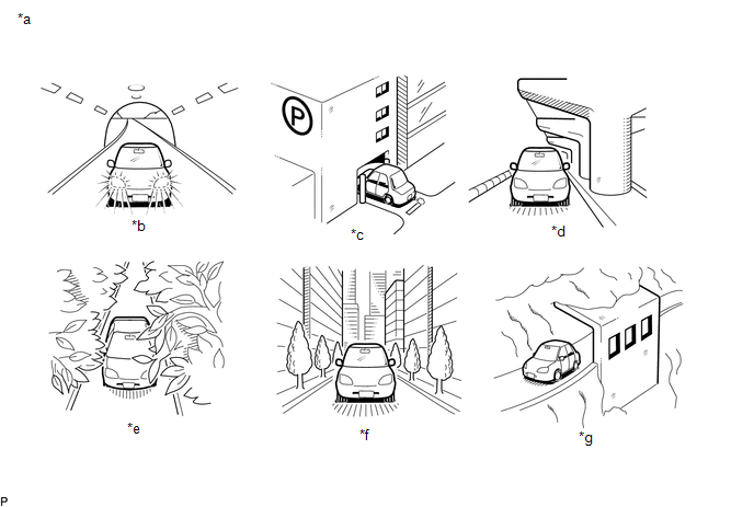
(a) Check if the vehicle is in an environment where reception is difficult due to something blocking the area above the vehicle.
|
*a |
Example |
*b |
In a tunnel |
|
*c |
In a building |
*d |
Under an overpass |
|
*e |
In a forest or on tree-lined path |
*f |
Between tall buildings |
|
*g |
Under a cliff or overhang |
- |
- |
HINT:
If the area above the vehicle is blocked, such as when in a building or tunnel, reception may not be possible.
OK:
Area above vehicle is not blocked.
| NG | .gif) |
END (MOVE VEHICLE TO LOCATION WHERE RECEPTION IS BETTER) |
|
.gif)
|
2. |
CHECK RADIO AND DISPLAY RECEIVER ASSEMBLY |
(a) Check if CH001 (free broadcast) can be received.
OK:
CH001 can be received.
| NG | |
GO TO STEP 6 |
|
|
3. |
CHECK DISPLAY SETTING |
(a) Check the display screen.
|
Result |
Proceed to |
|---|---|
|
"SAT Ch Unauth" is displayed. |
A |
|
"-----" is displayed. |
B |
|
None of the displays above are shown. |
C |
| B | |
THERE IS NO SONG/PROGRAM TITLE OR ARTIST NAME/FEATURE ASSOCIATED WITH CHANNEL AT THAT TIME |
| C | |
GO TO STEP 6 |
|
|
4. |
CHECK CONTRACT CONDITIONS |
(a) Check if the pay-type contract has been extended, or if the contract period has ended.
OK:
Pay-type contract is valid.
| NG | |
TO RECEIVE PAY-TYPE BROADCASTS, CONTRACT MUST BE MADE WITH SATELLITE RADIO COMPANY |
|
|
5. |
PERFORM ACTIVATION REFRESH |
(a) Perform activation refresh by referring to the satellite radio company web site (http://www.siriusxm.com).
OK:
Malfunction disappears.
HINT:
The SiriusXM radio ID that is necessary to perform activation refresh is displayed when CH000 is selected on the satellite radio.
| OK | |
END |
| NG | |
PROCEED TO NEXT SUSPECTED AREA SHOWN IN PROBLEM SYMPTOMS TABLE |
|
6. |
CHECK DISPLAY |
(a) Check the display screen.
|
Result |
Proceed to |
|---|---|
|
"SAT Ck Antenna" is displayed. |
A |
|
"SAT No Signal" is displayed. |
B |
|
"Loading" is displayed. |
|
|
"SAT Ch Off Air" is displayed. |
C |
|
After "SAT Ch Unavail" is displayed, display automatically switches to CH001. |
D |
|
None of the displays above are shown. |
E |
| B | |
END (MOVE VEHICLE TO LOCATION WHERE RECEPTION IS BETTER) |
| C | |
CHANNEL IS CURRENTLY NOT BEING BROADCASTED. BROADCAST CAN BE LISTENED TO OR VIEWED WHEN IT IS BACK ON AIR. (CHECK WITH RADIO STATION) |
| D | |
CHANNEL BROADCAST HAS ENDED (CHECK WITH RADIO STATION) |
| E | |
GO TO STEP 14 |
|
|
7. |
CHECK ANTENNA CORD SUB-ASSEMBLY |
(a) Replace the antenna cord sub-assembly with a new or known good one and check if radio broadcasts can be received normally.
Click here
.gif)
OK:
Radio broadcasts can be received normally.
|
Result |
Proceed to |
|---|---|
|
OK |
A |
|
NG (for TMMT Made) |
B |
|
NG (for TMC Made) |
C |
| A | |
END |
| C | |
GO TO STEP 11 |
|
|
8. |
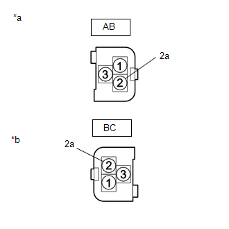
CHECK NO. 2 ANTENNA CORD SUB-ASSEMBLY |
|
(a) Disconnect the No. 2 antenna cord sub-assembly connector from the antenna cord sub-assembly. |
|
.png)
(b) Disconnect the No. 2 antenna cord sub-assembly connector from the No. 3 antenna Cord sub-assembly.
(c) Measure the resistance according to the value(s) in the table below.
Standard Resistance:
|
Tester Connection |
Condition |
Specified Condition |
|---|---|---|
|
AB-2 - BC-2 |
Always |
Below 1 Ω |
|
AB-2a - BC-2a |
Always |
Below 1 Ω |
|
AB-2 - Body ground |
Always |
10 kΩ or higher |
|
AB-2a - Body ground |
Always |
10 kΩ or higher |
| NG | |
REPLACE NO. 2 ANTENNA CORD SUB-ASSEMBLY |
|
|
9. |
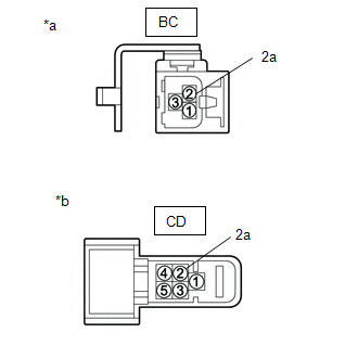
CHECK NO. 3 ANTENNA CORD SUB-ASSEMBLY |
|
(a) Disconnect the No. 3 antenna cord sub-assembly connector from the No. 2 antenna cord sub-assembly. |
|
.png)
(b) Disconnect the No. 3 antenna cord sub-assembly connector from the roof antenna assembly.
(c) Measure the resistance according to the value(s) in the table below.
Standard Resistance:
|
Tester Connection |
Condition |
Specified Condition |
|---|---|---|
|
BC-2 - CD-3 |
Always |
Below 1 Ω |
|
BC-2a - CD-3a |
Always |
Below 1 Ω |
|
BC-2 - Body ground |
Always |
10 kΩ or higher |
|
BC-2a - Body ground |
Always |
10 kΩ or higher |
| NG | |
REPLACE NO. 3 ANTENNA CORD SUB-ASSEMBLY |
|
|
10. |
REPLACE ROOF ANTENNA ASSEMBLY |
(a) Replace the roof antenna assembly with a new or known good one and check if radio broadcasts can be received normally.
Click here
OK:
Radio broadcasts can be received normally.
| OK | |
END |
| NG | |
PROCEED TO NEXT SUSPECTED AREA SHOWN IN PROBLEM SYMPTOMS TABLE |
|
11. |
CHECK NO. 2 ANTENNA CORD SUB-ASSEMBLY |
|
(a) Disconnect the No. 2 antenna cord sub-assembly connector from the antenna cord sub-assembly. |
|
(b) Disconnect the No. 2 antenna cord sub-assembly connector from the No. 3 antenna Cord sub-assembly.
(c) Measure the resistance according to the value(s) in the table below.
Standard Resistance:
|
Tester Connection |
Condition |
Specified Condition |
|---|---|---|
|
AB-3 - BC-2 |
Always |
Below 1 Ω |
|
AB-3a - BC-2a |
Always |
Below 1 Ω |
|
AB-3 - Body ground |
Always |
10 kΩ or higher |
|
AB-3a - Body ground |
Always |
10 kΩ or higher |
| NG | |
REPLACE NO. 2 ANTENNA CORD SUB-ASSEMBLY |
|
|
12. |
CHECK NO. 3 ANTENNA CORD SUB-ASSEMBLY |
|
(a) Disconnect the No. 3 antenna cord sub-assembly connector from the No. 2 antenna cord sub-assembly. |
|
(b) Disconnect the No. 3 antenna cord sub-assembly connector from the roof antenna assembly.
(c) Measure the resistance according to the value(s) in the table below.
Standard Resistance:
|
Tester Connection |
Condition |
Specified Condition |
|---|---|---|
|
BC-2 - CD-2 |
Always |
Below 1 Ω |
|
BC-2a - CD-2a |
Always |
Below 1 Ω |
|
BC-2 - Body ground |
Always |
10 kΩ or higher |
|
BC-2a - Body ground |
Always |
10 kΩ or higher |
| NG | |
REPLACE NO. 3 ANTENNA CORD SUB-ASSEMBLY |
|
|
13. |
REPLACE ROOF ANTENNA ASSEMBLY |
(a) Replace the telephone antenna assembly with a new or known good one and check if radio broadcasts can be received normally.
Click here
OK:
Radio broadcasts can be received normally.
| OK | |
END |
| NG | |
PROCEED TO NEXT SUSPECTED AREA SHOWN IN PROBLEM SYMPTOMS TABLE |
|
14. |
CHECK CURRENTLY SELECTED CHANNEL |
(a) Check if CH000 is currently selected.
OK:
CH000 is selected.
| OK | |
END (CH000 HAS NO SOUND. SELECT ANOTHER CHANNEL.) |
| NG | |
PROCEED TO NEXT SUSPECTED AREA SHOWN IN PROBLEM SYMPTOMS TABLE |
 HD Radio Tuner Malfunction (B1551,B158D,B15A0,B15B0,B15B3,B15B7,B15BA)
DESCRIPTION
These DTCs are stored when a malfunction occurs in the radio and display receiver
assembly.
DTC No.
Detection Item
DTC Detection Condition
T ...
 Satellite Radio Broadcast cannot be Selected or After Selecting Broadcast, Broadcast
cannot be Added into Memory
Satellite Radio Broadcast cannot be Selected or After Selecting Broadcast, Broadcast
cannot be Added into Memory
CAUTION / NOTICE / HINT
NOTICE:
Some satellite radio broadcasts require payment. A contract must be made between
a satellite radio company and the user. If the contract expires, it will not be
p ...
Other materials:
Toyota CH-R Service Manual > Door Control Switch: Removal
REMOVAL
PROCEDURE
1. REMOVE MULTIPLEX NETWORK MASTER SWITCH ASSEMBLY WITH FRONT ARMREST BASE UPPER
PANEL (for Driver Side)
Click here
2. REMOVE POWER WINDOW REGULATOR SWITCH ASSEMBLY WITH FRONT ARMREST BASE UPPER
PANEL (for Front Passenger Side)
Click here
3. REMOVE MULTIPLEX NETWO ...
Toyota CH-R Service Manual > Front Door Belt Moulding: Components
COMPONENTS
ILLUSTRATION
*1
FRONT DOOR BELT MOULDING ASSEMBLY
*2
FRONT DOOR GLASS SUB-ASSEMBLY
*3
FRONT DOOR SERVICE HOLE COVER
-
-
N*m (kgf*cm, ft.*lbf) : Specified torque
...
Toyota C-HR (AX20) 2023-2026 Owner's Manual
Toyota CH-R Owners Manual
- For safety and security
- Instrument cluster
- Operation of each component
- Driving
- Interior features
- Maintenance and care
- When trouble arises
- Vehicle specifications
- For owners
Toyota CH-R Service Manual
- Introduction
- Maintenance
- Audio / Video
- Cellular Communication
- Navigation / Multi Info Display
- Park Assist / Monitoring
- Brake (front)
- Brake (rear)
- Brake Control / Dynamic Control Systems
- Brake System (other)
- Parking Brake
- Axle And Differential
- Drive Shaft / Propeller Shaft
- K114 Cvt
- 3zr-fae Battery / Charging
- Networking
- Power Distribution
- Power Assist Systems
- Steering Column
- Steering Gear / Linkage
- Alignment / Handling Diagnosis
- Front Suspension
- Rear Suspension
- Tire / Wheel
- Tire Pressure Monitoring
- Door / Hatch
- Exterior Panels / Trim
- Horn
- Lighting (ext)
- Mirror (ext)
- Window / Glass
- Wiper / Washer
- Door Lock
- Heating / Air Conditioning
- Interior Panels / Trim
- Lighting (int)
- Meter / Gauge / Display
- Mirror (int)
- Power Outlets (int)
- Pre-collision
- Seat
- Seat Belt
- Supplemental Restraint Systems
- Theft Deterrent / Keyless Entry

0.0119