Toyota CH-R Service Manual: Horn Circuit
DESCRIPTION
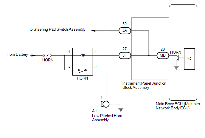
When the theft deterrent system is switched from the armed state to the alarm sounding state, the main body ECU (multiplex network body ECU) transmits a signal to cause the horns to sound at intervals of 0.4 seconds.
WIRING DIAGRAM
CAUTION / NOTICE / HINT
NOTICE:
- Before replacing the main body ECU (multiplex network body ECU), refer
to REGISTRATION*1.
Click here
.gif)
*1: w/ Smart Key System
- Inspect the fuses for circuits related to this system before performing the following procedure.
PROCEDURE
|
1. |
INSPECT HORNS |
(a) Press the horn switch and check if the horns sound.
|
Result |
Proceed to |
|---|---|
|
Horns sound |
A |
|
Horns do not sound |
B |
| B | .gif) |
GO TO HORN SYSTEM |
|
.gif)
|
2. |
INSPECT INSTRUMENT PANEL JUNCTION BLOCK ASSEMBLY |
(a) Remove the main body ECU (multiplex network body ECU).
Click here
|
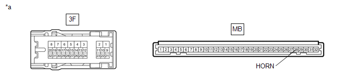
*a |
Component without harness connected (Instrument Panel Junction Block Assembly) |
- |
- |
(b) Disconnect the instrument panel junction block assembly connector.
(c) Measure the resistance according to the value(s) in the table below.
Standard Resistance:
|
Tester Connection |
Condition |
Specified Condition |
|---|---|---|
|
3F-27 - MB-28 (HORN) |
Always |
Below 1 Ω |
| OK | |
REPLACE MAIN BODY ECU (MULTIPLEX NETWORK BODY ECU) |
| NG | |
REPLACE INSTRUMENT PANEL JUNCTION BLOCK ASSEMBLY |
 Engine Hood Courtesy Switch Circuit
DESCRIPTION
The hood courtesy switch is built into the hood lock assembly. This switch turns
on when the hood is closed and turns off when the hood is opened.
WIRING DIAGRAM
CAUTION / NOTICE / ...
 Security Horn Circuit
DESCRIPTION
When the theft deterrent system is switched from the armed state to the alarm
sounding state, the main body ECU (multiplex network body ECU) transmits a signal
to cause the security h ...
Other materials:
Toyota CH-R Service Manual > Rear Suspension Member: Installation
INSTALLATION
PROCEDURE
1. INSTALL HOLE PLUG
(a) Install the 7 hole plugs to the rear suspension member sub-assembly as shown
in the illustration.
2. INSTALL REAR SUSPENSION MEMBER HOLE COVER
(a) Install the 4 rear suspension member hole covers to the rear suspension member
sub-assembly.
3. ...
Toyota CH-R Owners Manual > Steps to take in an emergency: If your vehicle overheats
The following may indicate that your vehicle is overheating.
The needle of the engine coolant temperature gauge enters the red zone or
a loss of engine power is experienced (for example, the vehicle speed does not
increase).
Steam comes out from under the hood.
Correction procedures
...
Toyota C-HR (AX20) 2023-2026 Owner's Manual
Toyota CH-R Owners Manual
- For safety and security
- Instrument cluster
- Operation of each component
- Driving
- Interior features
- Maintenance and care
- When trouble arises
- Vehicle specifications
- For owners
Toyota CH-R Service Manual
- Introduction
- Maintenance
- Audio / Video
- Cellular Communication
- Navigation / Multi Info Display
- Park Assist / Monitoring
- Brake (front)
- Brake (rear)
- Brake Control / Dynamic Control Systems
- Brake System (other)
- Parking Brake
- Axle And Differential
- Drive Shaft / Propeller Shaft
- K114 Cvt
- 3zr-fae Battery / Charging
- Networking
- Power Distribution
- Power Assist Systems
- Steering Column
- Steering Gear / Linkage
- Alignment / Handling Diagnosis
- Front Suspension
- Rear Suspension
- Tire / Wheel
- Tire Pressure Monitoring
- Door / Hatch
- Exterior Panels / Trim
- Horn
- Lighting (ext)
- Mirror (ext)
- Window / Glass
- Wiper / Washer
- Door Lock
- Heating / Air Conditioning
- Interior Panels / Trim
- Lighting (int)
- Meter / Gauge / Display
- Mirror (int)
- Power Outlets (int)
- Pre-collision
- Seat
- Seat Belt
- Supplemental Restraint Systems
- Theft Deterrent / Keyless Entry

0.008