Toyota CH-R Service Manual: Security Horn Circuit
DESCRIPTION
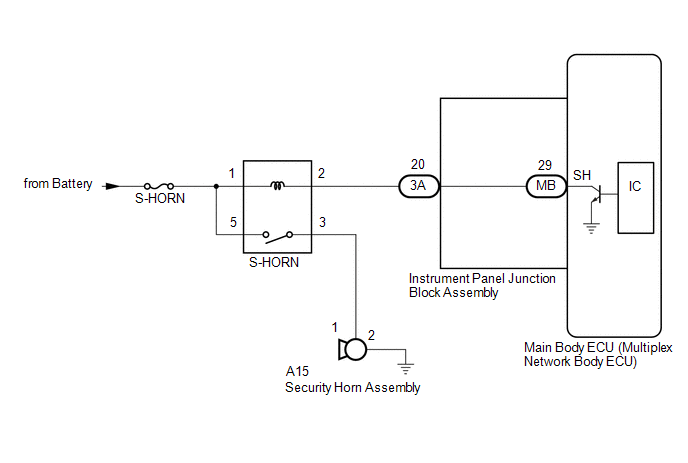
When the theft deterrent system is switched from the armed state to the alarm sounding state, the main body ECU (multiplex network body ECU) transmits a signal to cause the security horn assembly to sound at intervals of 0.4 seconds.
WIRING DIAGRAM
CAUTION / NOTICE / HINT
NOTICE:
- Before replacing the main body ECU (multiplex network body ECU), refer
to REGISTRATION*1.
Click here
.gif)
*1: w/ Smart Key System
- Inspect the fuses for circuits related to this system before performing the following procedure.
PROCEDURE
|
1. |
PERFORM ACTIVE TEST USING TECHSTREAM (SECURITY HORN) |
(a) Connect the Techstream to the DLC3.
(b) Turn the ignition switch to ON.
(c) Turn the Techstream on.
(d) Enter the following menus: Body Electrical / Main Body / Active Test.
(e) Perform the Active Test according to the display on the Techstream.
Body Electrical > Main Body > Active Test|
Tester Display |
Measurement Item |
Control Range |
Diagnostic Note |
|---|---|---|---|
|
Security Horn |
Security horn Assembly |
OFF/ON |
- |
|
Tester Display |
|---|
|
Security Horn |
OK:
The security horn assembly sounds and stops correctly when operated through the Techstream.
| OK | .gif) |
REPLACE MAIN BODY ECU (MULTIPLEX NETWORK BODY ECU) |
|
.gif)
|
2. |
INSPECT SECURITY HORN ASSEMBLY |
(a) Remove the security horn assembly.
Click here
(b) Inspect the security horn assembly.
Click here
| NG | |
REPLACE SECURITY HORN ASSEMBLY |
|
|
3. |
INSPECT S-HORN RELAY |
(a) Remove the S-HORN relay from the No. 4 relay block assembly.
(b) Inspect the S-HORN relay.
Click here
| NG | |
REPLACE S-HORN RELAY |
|
|
4. |
INSPECT INSTRUMENT PANEL JUNCTION BLOCK ASSEMBLY |
(a) Remove the main body ECU (multiplex network body ECU).
Click here
|
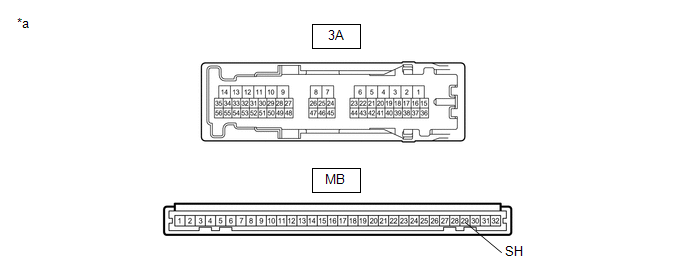
*a |
Component without harness connected (Instrument Panel Junction Block Assembly) |
- |
- |
(b) Disconnect the 3A instrument panel junction block assembly connector.
(c) Measure the resistance according to the value(s) in the table below.
Standard Resistance:
|
Tester Connection |
Condition |
Specified Condition |
|---|---|---|
|
3A-20 - MB-29 (SH) |
Always |
Below 1 Ω |
| NG | |
REPLACE INSTRUMENT PANEL JUNCTION BLOCK ASSEMBLY |
|
|
5. |
CHECK HARNESS AND CONNECTOR (BATTERY - S-HORN RELAY) |
(a) Remove the S-HORN relay from the No. 4 relay block assembly.
|
(b) Measure the voltage according to the value(s) in the table below. Standard Voltage:
|
|
| NG | |
REPAIR OR REPLACE HARNESS OR CONNECTOR |
|
|
6. |
CHECK HARNESS AND CONNECTOR (S-HORN RELAY - SECURITY HORN ASSEMBLY) |
(a) Remove the S-HORN relay from the No. 4 relay block assembly.
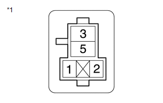
(b) Disconnect the A15 security horn assembly connector.
|
(c) Measure the resistance according to the value(s) in the table below. Standard Resistance:
|
|
| NG | |
REPAIR OR REPLACE HARNESS OR CONNECTOR |
|
|
7. |
CHECK HARNESS AND CONNECTOR (S-HORN RELAY - INSTRUMENT PANEL JUNCTION BLOCK ASSEMBLY) |
(a) Remove the S-HORN relay from the No. 4 relay block assembly.
(b) Disconnect the 3A instrument panel junction block assembly connector.
|
(c) Measure the resistance according to the value(s) in the table below. Standard Resistance:
|
|
| OK | |
REPLACE MAIN BODY ECU (MULTIPLEX NETWORK BODY ECU) |
| NG | |
REPAIR OR REPLACE HARNESS OR CONNECTOR |
 Horn Circuit
DESCRIPTION
When the theft deterrent system is switched from the armed state to the alarm
sounding state, the main body ECU (multiplex network body ECU) transmits a signal
to cause the horns to s ...
 Improper Operation
DESCRIPTION
When the theft deterrent system operates by itself, it could be due to something
such as a short circuit in the courtesy light switch of any of the doors or the
hood causing a signal ...
Other materials:
Toyota CH-R Service Manual > Main Body Ecu: Components
COMPONENTS
ILLUSTRATION
*A
except Cold Area Specification Vehicles
*B
for Cold Area Specification Vehicles
*1
INSTRUMENT PANEL JUNCTION BLOCK ASSEMBLY WITH MAIN BODY ECU
*2
NO. 3 INSTRUMENT PANEL TO COW ...
Toyota CH-R Service Manual > Front Wiper Motor: Installation
INSTALLATION
CAUTION / NOTICE / HINT
NOTICE:
Make sure to hold the front wiper arm while lifting it as lifting the front wiper
arm by the front wiper blade may damage or deform the front wiper blade.
PROCEDURE
1. INSTALL WINDSHIELD WIPER MOTOR ASSEMBLY
(a) for USA and Canada:
(1) Install th ...
Toyota C-HR (AX20) 2023-2026 Owner's Manual
Toyota CH-R Owners Manual
- For safety and security
- Instrument cluster
- Operation of each component
- Driving
- Interior features
- Maintenance and care
- When trouble arises
- Vehicle specifications
- For owners
Toyota CH-R Service Manual
- Introduction
- Maintenance
- Audio / Video
- Cellular Communication
- Navigation / Multi Info Display
- Park Assist / Monitoring
- Brake (front)
- Brake (rear)
- Brake Control / Dynamic Control Systems
- Brake System (other)
- Parking Brake
- Axle And Differential
- Drive Shaft / Propeller Shaft
- K114 Cvt
- 3zr-fae Battery / Charging
- Networking
- Power Distribution
- Power Assist Systems
- Steering Column
- Steering Gear / Linkage
- Alignment / Handling Diagnosis
- Front Suspension
- Rear Suspension
- Tire / Wheel
- Tire Pressure Monitoring
- Door / Hatch
- Exterior Panels / Trim
- Horn
- Lighting (ext)
- Mirror (ext)
- Window / Glass
- Wiper / Washer
- Door Lock
- Heating / Air Conditioning
- Interior Panels / Trim
- Lighting (int)
- Meter / Gauge / Display
- Mirror (int)
- Power Outlets (int)
- Pre-collision
- Seat
- Seat Belt
- Supplemental Restraint Systems
- Theft Deterrent / Keyless Entry

0.0095