Toyota CH-R Service Manual: Tire Pressure Warning Receiver
Components
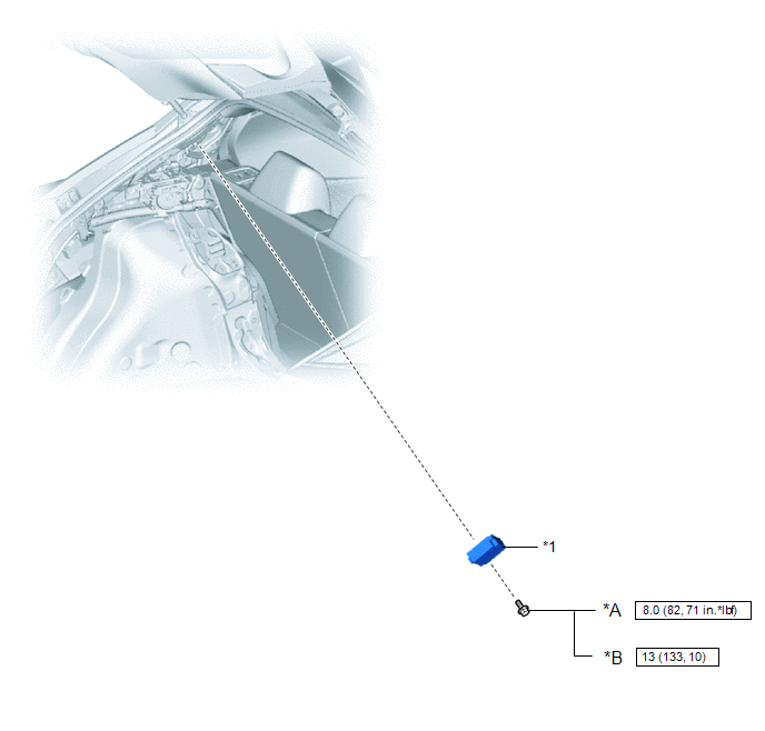
COMPONENTS
ILLUSTRATION
|
*A |
for Type A |
*B |
for Type B |
|
*1 |
TIRE PRESSURE WARNING ECU AND RECEIVER |
- |
- |
.png) |
N*m (kgf*cm, ft.*lbf): Specified torque |
- |
- |
Removal
REMOVAL
CAUTION / NOTICE / HINT
The necessary procedures (adjustment, calibration, initialization or registration) that must be performed after parts are removed and installed, or replaced during tire pressure warning ECU and receiver removal/installation are shown below.
|
Replacement Part or Procedure |
Necessary Procedures |
Effects/Inoperative when not Performed |
Link |
|---|---|---|---|
|
Replacement of tire pressure warning ECU and receiver |
|
|
|
NOTICE:
When replacing the tire pressure warning ECU and receiver, read the transmitter IDs stored in the old ECU using the Techstream and write them down before removal.
Click here
.gif)
PROCEDURE
1. REMOVE DECK TRIM SIDE PANEL ASSEMBLY LH
Click here
2. REMOVE TIRE PRESSURE WARNING ECU AND RECEIVER
NOTICE:
- Do not drop, strike or otherwise subject the tire pressure warning ECU and receiver to impact.
- If the tire pressure warning ECU and receiver is subjected to an impact, replace it with a new one.
|
(a) Remove the bolt. |
|
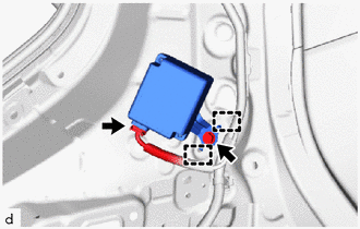
(b) Disengage the 2 guides.
(c) Disconnect the connector to remove the tire pressure warning ECU and receiver.
Installation
INSTALLATION
PROCEDURE
1. INSTALL TIRE PRESSURE WARNING ECU AND RECEIVER
NOTICE:
- Do not drop, strike or otherwise subject the tire pressure warning ECU and receiver to impact.
- If the tire pressure warning ECU and receiver is subjected to an impact, replace it with a new one.
|
(a) Connect the connector. |
|
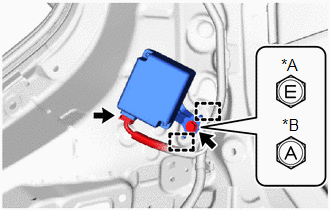
(b) Engage the 2 guides and install the tire pressure warning ECU and receiver with the bolt.
Torque:
for Type A :
8.0 N·m {82 kgf·cm, 71 in·lbf}
for Type B :
13 N·m {133 kgf·cm, 10 ft·lbf}
2. INSTALL DECK TRIM SIDE PANEL ASSEMBLY LH
Click here
.gif)
3. REGISTER TRANSMITTER ID
Click here
4. INSPECT TIRE PRESSURE WARNING SYSTEM
Click here
5. PERFORM INITIALIZATION
Click here


Other materials:
Toyota CH-R Service Manual > Back Door: Reassembly
REASSEMBLY
PROCEDURE
1. INSTALL NO. 1 BACK DOOR EMBLEM
Click here
2. INSTALL NO. 2 BACK DOOR NAME PLATE
Click here
3. INSTALL NO. 1 BACK DOOR NAME PLATE (w/ Brand Mark)
Click here
4. INSTALL REAR LIGHT PACKING
Click here
5. INSTALL REAR LIGHT ASSEMBLY LH
Click here
6. ...
Toyota CH-R Service Manual > Meter / Gauge System: Engine Oil Pressure Switch Circuit
DESCRIPTION
The combination meter assembly and engine oil pressure switch assembly are connected
via direct line. The combination meter assembly determines the engine oil pressure
based on the engine oil pressure switch ON/OFF signal.
HINT:
The combination meter assembly receives vari ...
Toyota C-HR (AX20) 2023-2026 Owner's Manual
Toyota CH-R Owners Manual
- For safety and security
- Instrument cluster
- Operation of each component
- Driving
- Interior features
- Maintenance and care
- When trouble arises
- Vehicle specifications
- For owners
Toyota CH-R Service Manual
- Introduction
- Maintenance
- Audio / Video
- Cellular Communication
- Navigation / Multi Info Display
- Park Assist / Monitoring
- Brake (front)
- Brake (rear)
- Brake Control / Dynamic Control Systems
- Brake System (other)
- Parking Brake
- Axle And Differential
- Drive Shaft / Propeller Shaft
- K114 Cvt
- 3zr-fae Battery / Charging
- Networking
- Power Distribution
- Power Assist Systems
- Steering Column
- Steering Gear / Linkage
- Alignment / Handling Diagnosis
- Front Suspension
- Rear Suspension
- Tire / Wheel
- Tire Pressure Monitoring
- Door / Hatch
- Exterior Panels / Trim
- Horn
- Lighting (ext)
- Mirror (ext)
- Window / Glass
- Wiper / Washer
- Door Lock
- Heating / Air Conditioning
- Interior Panels / Trim
- Lighting (int)
- Meter / Gauge / Display
- Mirror (int)
- Power Outlets (int)
- Pre-collision
- Seat
- Seat Belt
- Supplemental Restraint Systems
- Theft Deterrent / Keyless Entry

0.0102