Toyota CH-R Service Manual: Power Window Switch Malfunction (B2312)
DESCRIPTION
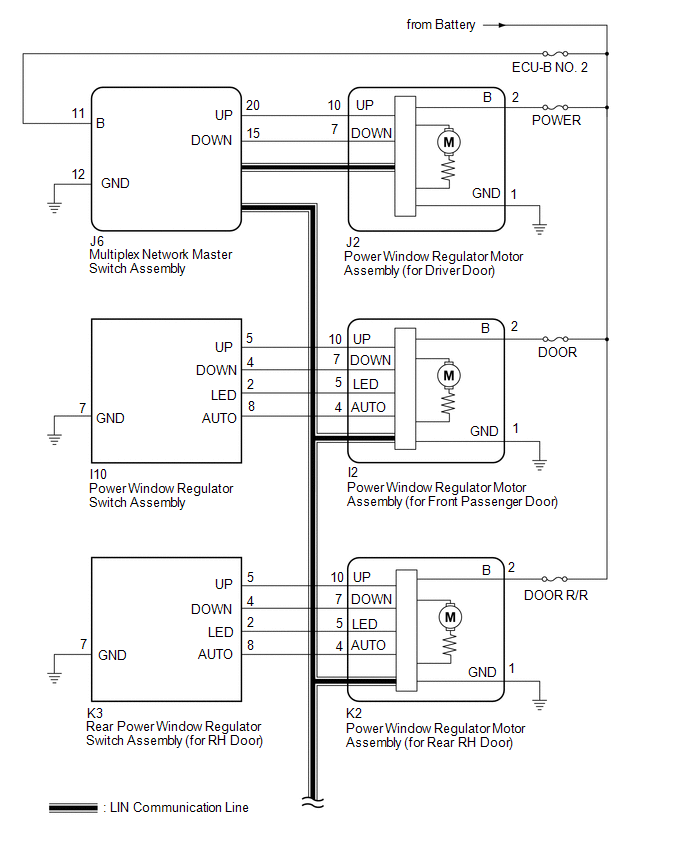
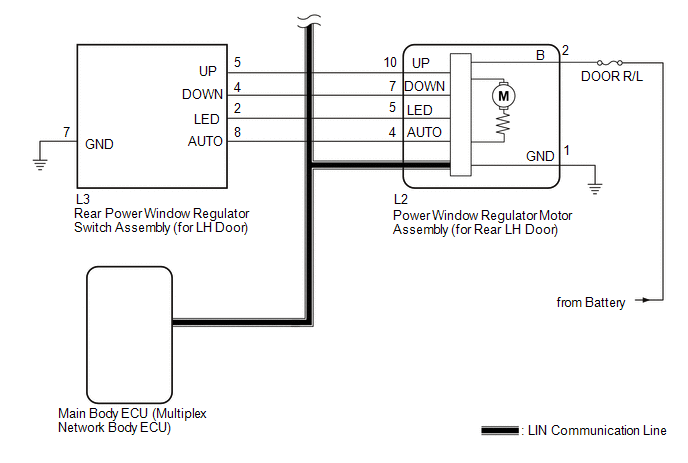
The power window regulator motor assemblies are operated by the multiplex network master switch assembly, power window regulator switch assembly or rear power window regulator switch assemblies. The power window regulator motor assemblies have motor, regulator and ECU functions.
This DTC is stored when the ECU built into a power window regulator motor assembly and multiplex network master switch assembly determine that the multiplex network master switch assembly, power window regulator switch assembly or rear power window regulator switch assembly is stuck.
Master Switch|
DTC No. |
Detection Item |
DTC Detection Condition |
Trouble Area |
|---|---|---|---|
|
B2312 |
Power Window Switch Malfunction |
|
Multiplex network master switch assembly |
|
Vehicle Condition |
||||
|---|---|---|---|---|
|
Pattern 1 |
Pattern 2 |
Pattern 3 |
||
|
Diagnosis Condition |
Ignition switch ON |
○ |
○ |
○ |
|
Malfunction Status |
Multiplex network master switch assembly stuck |
○ |
- |
- |
|
Multiplex network master switch assembly held in same position |
- |
○ |
- |
|
|
Multiplex network master switch assembly operated |
- |
- |
○ |
|
|
Detection Time |
- |
More than 20 seconds |
20 seconds or more |
|
|
Number of Trips |
1 trip |
1 trip |
1 trip |
|
HINT:
DTC will be output when conditions for either of the patterns in the table above are met.
D-Door Motor|
DTC No. |
Detection Item |
DTC Detection Condition |
Trouble Area |
|---|---|---|---|
|
B2312 |
Power Window Switch Malfunction |
|
|
|
Vehicle Condition |
|||
|---|---|---|---|
|
Pattern 1 |
Pattern 2 |
||
|
Diagnosis Condition |
Ignition switch ON |
○ |
○ |
|
Malfunction Status |
Multiplex network master switch assembly stuck |
○ |
- |
|
Multiplex network master switch assembly held in same position |
- |
○ |
|
|
Detection Time |
- |
More than 20 seconds |
|
|
Number of Trips |
1 trip |
1 trip |
|
HINT:
DTC will be output when conditions for either of the patterns in the table above are met.
P-Door Motor|
DTC No. |
Detection Item |
DTC Detection Condition |
Trouble Area |
|---|---|---|---|
|
B2312 |
Power Window Switch Malfunction |
|
|
|
Vehicle Condition |
|||
|---|---|---|---|
|
Pattern 1 |
Pattern 2 |
||
|
Diagnosis Condition |
Ignition switch ON |
○ |
○ |
|
Malfunction Status |
Power window regulator switch assembly stuck |
○ |
- |
|
Power window regulator switch assembly held in same position |
- |
○ |
|
|
Detection Time |
- |
More than 20 seconds |
|
|
Number of Trips |
1 trip |
1 trip |
|
HINT:
DTC will be output when conditions for either of the patterns in the table above are met.
RL-Door Motor|
DTC No. |
Detection Item |
DTC Detection Condition |
Trouble Area |
|---|---|---|---|
|
B2312 |
Power Window Switch Malfunction |
|
|
|
Vehicle Condition |
|||
|---|---|---|---|
|
Pattern 1 |
Pattern 2 |
||
|
Diagnosis Condition |
Ignition switch ON |
○ |
○ |
|
Malfunction Status |
Rear power window regulator switch assembly (for LH door) stuck |
○ |
- |
|
Power window regulator switch assembly rear (for LH door) held in same position |
- |
○ |
|
|
Detection Time |
- |
More than 20 seconds |
|
|
Number of Trips |
1 trip |
1 trip |
|
HINT:
DTC will be output when conditions for either of the patterns in the table above are met.
RR-Door Motor|
DTC No. |
Detection Item |
DTC Detection Condition |
Trouble Area |
|---|---|---|---|
|
B2312 |
Power Window Switch Malfunction |
|
|
|
Vehicle Condition |
|||
|---|---|---|---|
|
Pattern 1 |
Pattern 2 |
||
|
Diagnosis Condition |
Ignition switch ON |
○ |
○ |
|
Malfunction Status |
Rear power window regulator switch assembly (for RH door) stuck |
○ |
- |
|
Power window regulator switch assembly (for RH door) held in same position for more than 20 seconds |
- |
○ |
|
|
Detection Time |
- |
More than 20 seconds |
|
|
Number of Trips |
1 trip |
1 trip |
|
HINT:
DTC will be output when conditions for either of the patterns in the table above are met.
WIRING DIAGRAM
CAUTION / NOTICE / HINT
NOTICE:
- DTC B2312 is stored in the multiplex network master switch assembly and in each power window regulator motor assembly.
- If a power window regulator motor assembly has been replaced with a
new one, initialize the power window control system.
Click here
.gif)
- Inspect the fuses for circuits related to this system before performing the following procedure.
- The power window control system uses the LIN communication system. Inspect
the communication function by following How to Proceed with Troubleshooting.
Troubleshoot the power window control system after confirming that the communication
system is functioning properly.
Click here
HINT:
If DTC B2312 is not output again after the DTC has been cleared, the DTC was stored due to the switch being held in the same position continuously.
PROCEDURE
|
1. |
CHECK FOR DTC |
(a) Clear the DTCs.
Click here
(b) Check for DTCs.
Click here
OK:
DTC B2312 is not output.
| OK | .gif) |
END (DTC WAS STORED DUE TO SWITCH BEING OPERATED FOR 20 SECONDS OR MORE) |
|
.gif)
|
2. |
CHECK DTC OUTPUT |
(a) Check the parts from which this DTC has been output.
|
Result |
Proceed to |
|---|---|
|
DTC output from multiplex network master switch assembly |
A |
|
DTC output from power window regulator motor assembly (for driver door) |
B |
|
DTC output from power window regulator motor assembly (for front passenger door) |
C |
|
DTC output from power window regulator motor assembly (for rear LH door) |
D |
|
DTC output from power window regulator motor assembly (for rear RH door) |
E |
| A | |
REPLACE MULTIPLEX NETWORK MASTER SWITCH ASSEMBLY |
| C | |
GO TO STEP 7 |
| D | |
GO TO STEP 10 |
| E | |
GO TO STEP 13 |
|
|
3. |
READ VALUE USING TECHSTREAM (D-DOOR MOTOR) |
(a) Connect the Techstream to the DLC3.
(b) Turn the ignition switch to ON.
(c) Turn the Techstream on.
(d) Enter the following menus: Body Electrical / D-Door Motor / Data List.
(e) Read the Data List according to the display on the Techstream.
Body Electrical > D-Door Motor > Data List|
Tester Display |
Measurement Item |
Range |
Normal Condition |
Diagnostic Note |
|---|---|---|---|---|
|
D Door P/W Up SW |
Driver door power window manual up switch signal |
OFF or ON |
OFF: Driver door power window manual up switch not being operated ON: Driver door power window manual up switch being operated |
- |
|
D Door P/W Down SW |
Driver door power window manual down switch signal |
OFF or ON |
OFF: Driver door power window manual down switch not being operated ON: Driver door power window manual down switch being operated |
- |
|
Tester Display |
|---|
|
D Door P/W Up SW |
|
D Door P/W Down SW |
OK:
On the Techstream screen, ON or OFF is displayed accordingly.
| OK | |
REPLACE POWER WINDOW REGULATOR MOTOR ASSEMBLY (FOR DRIVER DOOR) |
|
|
4. |
CHECK HARNESS AND CONNECTOR (MULTIPLEX NETWORK MASTER SWITCH ASSEMBLY - POWER WINDOW REGULATOR MOTOR ASSEMBLY (FOR DRIVER DOOR)) |
(a) Disconnect the J6 multiplex network master switch assembly connector.
(b) Disconnect the J2 power window regulator motor assembly (for driver door) connector.
(c) Measure the resistance according to the value(s) in the table below.
Standard Resistance:
|
Tester Connection |
Condition |
Specified Condition |
|---|---|---|
|
J6-20 (UP) or J2-10 (UP) - Body ground |
Always |
10 kΩ or higher |
|
J6-15 (DOWN) or J2-7 (DOWN) - Body ground |
Always |
10 kΩ or higher |
| NG | |
REPAIR OR REPLACE HARNESS OR CONNECTOR |
|
|
5. |
REPLACE MULTIPLEX NETWORK MASTER SWITCH ASSEMBLY |
(a) Replace the multiplex network master switch assembly.
Click here
|
|
6. |
CHECK FOR DTC |
(a) Clear the DTCs.
Click here
(b) Check for DTCs.
Click here
OK:
DTC B2312 is not output.
| OK | |
END (MULTIPLEX NETWORK MASTER SWITCH ASSEMBLY WAS DEFECTIVE) |
| NG | |
REPLACE POWER WINDOW REGULATOR MOTOR ASSEMBLY (FOR DRIVER DOOR) |
|
7. |
READ VALUE USING TECHSTREAM (P-DOOR MOTOR) |
(a) Connect the Techstream to the DLC3.
(b) Turn the ignition switch to ON.
(c) Turn the Techstream on.
(d) Enter the following menus: Body Electrical / P-Door Motor / Data List.
(e) Read the Data List according to the display on the Techstream.
Body Electrical > P-Door Motor > Data List|
Tester Display |
Measurement Item |
Range |
Normal Condition |
Diagnostic Note |
|---|---|---|---|---|
|
P Door P/W Auto SW |
Front passenger door power window auto switch signal |
OFF or ON |
OFF: Front passenger door power window auto up or auto down switch not being operated ON: Front passenger door power window auto up or auto down switch being operated |
- |
|
P Door P/W Up SW |
Front passenger door power window manual up switch signal |
OFF or ON |
OFF: Front passenger door power window manual up switch not being operated ON: Front passenger door power window manual up switch being operated |
- |
|
P Door P/W Down SW |
Front passenger door power window manual down switch signal |
OFF or ON |
OFF: Front passenger door power window manual down switch not being operated ON: Front passenger door power window manual down switch being operated |
- |
|
Tester Display |
|---|
|
P Door P/W Auto SW |
|
P Door P/W Up SW |
|
P Door P/W Down SW |
OK:
On the Techstream screen, ON or OFF is displayed accordingly.
| OK | |
REPLACE POWER WINDOW REGULATOR MOTOR ASSEMBLY (FOR FRONT PASSENGER DOOR) |
|
|
8. |
INSPECT POWER WINDOW REGULATOR SWITCH ASSEMBLY |
(a) Remove the power window regulator switch assembly.
Click here
(b) Inspect the power window regulator switch assembly.
Click here
| NG | |
REPLACE POWER WINDOW REGULATOR SWITCH ASSEMBLY |
|
|
9. |
CHECK HARNESS AND CONNECTOR (POWER WINDOW REGULATOR SWITCH ASSEMBLY - POWER WINDOW REGULATOR MOTOR ASSEMBLY (FOR FRONT PASSENGER DOOR)) |
(a) Disconnect the I2 power window regulator motor assembly (for front passenger door) connector.
(b) Measure the resistance according to the value(s) in the table below.
Standard Resistance:
|
Tester Connection |
Condition |
Specified Condition |
|---|---|---|
|
I10-5 (UP) or I2-10 (UP) - Body ground |
Always |
10 kΩ or higher |
|
I10-8 (AUTO) or I2-4 (AUTO) - Body ground |
Always |
10 kΩ or higher |
|
I10-4 (DOWN) or I2-7 (DOWN) - Body ground |
Always |
10 kΩ or higher |
| OK | |
REPLACE POWER WINDOW REGULATOR MOTOR ASSEMBLY (FOR FRONT PASSENGER DOOR) |
| NG | |
REPAIR OR REPLACE HARNESS OR CONNECTOR |
|
10. |
READ VALUE USING TECHSTREAM (RL-DOOR MOTOR) |
(a) Connect the Techstream to the DLC3.
(b) Turn the ignition switch to ON.
(c) Turn the Techstream on.
(d) Enter the following menus: Body Electrical / RL-Door Motor / Data List.
(e) Read the Data List according to the display on the Techstream.
Body Electrical > RL-Door Motor > Data List|
Tester Display |
Measurement Item |
Range |
Normal Condition |
Diagnostic Note |
|---|---|---|---|---|
|
RL Door P/W Auto SW |
Rear LH door power window auto switch signal |
OFF or ON |
OFF: Rear LH door power window auto up or auto down switch not being operated ON: Rear LH door power window auto up or auto down switch being operated |
- |
|
RL Door P/W Up SW |
Rear LH door power window manual up switch signal |
OFF or ON |
OFF: Rear LH door power window manual up switch not being operated ON: Rear LH door power window manual up switch being operated |
- |
|
RL Door P/W Down SW |
Rear LH door power window manual down switch signal |
OFF or ON |
OFF: Rear LH door power window manual down switch not being operated ON: Rear LH door power window manual down switch being operated |
- |
|
Tester Display |
|---|
|
RL Door P/W Auto SW |
|
RL Door P/W Up SW |
|
RL Door P/W Down SW |
OK:
On the Techstream screen, ON or OFF is displayed accordingly.
| OK | |
REPLACE POWER WINDOW REGULATOR MOTOR ASSEMBLY (FOR REAR LH DOOR) |
|
|
11. |
INSPECT REAR POWER WINDOW REGULATOR SWITCH ASSEMBLY (FOR LH DOOR) |
(a) Remove the rear power window regulator switch assembly (for LH door).
Click here
(b) Inspect the rear power window regulator switch assembly (for LH door).
Click here
| NG | |
REPLACE REAR POWER WINDOW REGULATOR SWITCH ASSEMBLY (FOR LH DOOR) |
|
|
12. |
CHECK HARNESS AND CONNECTOR (REAR POWER WINDOW REGULATOR SWITCH ASSEMBLY (FOR LH DOOR) - POWER WINDOW REGULATOR MOTOR ASSEMBLY (FOR REAR LH DOOR)) |
(a) Disconnect the L2 power window regulator motor assembly (for rear LH door) connector.
(b) Measure the resistance according to the value(s) in the table below.
Standard Resistance|
Tester Connection |
Condition |
Specified Condition |
|---|---|---|
|
L3-5 (UP) or L2-10 (UP) - Body ground |
Always |
10 kΩ or higher |
|
L3-4 (DOWN) or L2-7 (DOWN) - Body ground |
Always |
10 kΩ or higher |
|
L3-8 (AUTO) or L2-4 (AUTO) - Body ground |
Always |
10 kΩ or higher |
| OK | |
REPLACE POWER WINDOW REGULATOR MOTOR ASSEMBLY (FOR REAR LH DOOR) |
| NG | |
REPAIR OR REPLACE HARNESS OR CONNECTOR |
|
13. |
READ VALUE USING TECHSTREAM (RR-DOOR MOTOR) |
(a) Connect the Techstream to the DLC3.
(b) Turn the ignition switch to ON.
(c) Turn the Techstream on.
(d) Enter the following menus: Body Electrical / RR-Door Motor / Data List.
(e) Read the Data List according to the display on the Techstream.
Body Electrical > RR-Door Motor > Data List|
Tester Display |
Measurement Item |
Range |
Normal Condition |
Diagnostic Note |
|---|---|---|---|---|
|
RR Door P/W Auto SW |
Rear RH door power window auto switch signal |
OFF or ON |
OFF: Rear RH door power window auto up or auto down switch not being operated ON: Rear RH door power window auto up or auto down switch being operated |
- |
|
RR Door P/W Up SW |
Rear RH door power window manual up switch signal |
OFF or ON |
OFF: Rear RH door power window manual up switch not being operated ON: Rear RH door power window manual up switch being operated |
- |
|
RR Door P/W Down SW |
Rear RH door power window manual down switch signal |
OFF or ON |
OFF: Rear RH door power window manual down switch not being operated ON: Rear RH door power window manual down switch being operated |
- |
|
Tester Display |
|---|
|
RR Door P/W Auto SW |
|
RR Door P/W Up SW |
|
RR Door P/W Down SW |
OK:
On the Techstream screen, ON or OFF is displayed accordingly.
| OK | |
REPLACE POWER WINDOW REGULATOR MOTOR ASSEMBLY (FOR REAR RH DOOR) |
|
|
14. |
INSPECT REAR POWER WINDOW REGULATOR SWITCH ASSEMBLY (FOR RH DOOR) |
(a) Remove the rear power window regulator switch assembly (for RH door).
Click here
(b) Inspect the rear power window regulator switch assembly (for RH door).
Click here
| NG | |
REPLACE REAR POWER WINDOW REGULATOR SWITCH ASSEMBLY (FOR RH DOOR) |
|
|
15. |
CHECK HARNESS AND CONNECTOR (REAR POWER WINDOW REGULATOR SWITCH ASSEMBLY (FOR RH DOOR) - POWER WINDOW REGULATOR MOTOR ASSEMBLY (FOR REAR RH DOOR)) |
(a) Disconnect the K2 power window regulator motor assembly (for rear RH door) connector.
(b) Measure the resistance according to the value(s) in the table below.
Standard Resistance|
Tester Connection |
Condition |
Specified Condition |
|---|---|---|
|
K3-5 (UP) or K2-10 (UP) - Body ground |
Always |
10 kΩ or higher |
|
K3-4 (DOWN) or K2-7 (DOWN) - Body ground |
Always |
10 kΩ or higher |
|
K3-8 (AUTO) or K2-4 (AUTO) - Body ground |
Always |
10 kΩ or higher |
| OK | |
REPLACE POWER WINDOW REGULATOR MOTOR ASSEMBLY (FOR REAR RH DOOR) |
| NG | |
REPAIR OR REPLACE HARNESS OR CONNECTOR |
 Power Window Motor Malfunction (B2311)
DESCRIPTION
The power window regulator motor assemblies are operated by the multiplex network
master switch assembly, power window regulator switch assembly or rear power window
regulator switch ...
 Glass Position Initialization Incomplete (B2313)
DESCRIPTION
The power window regulator motor assemblies are operated by the multiplex network
master switch assembly, power window regulator switch assembly or rear power window
regulator switch ...
Other materials:
Toyota CH-R Service Manual > Lighting System: Diagnosis System
DIAGNOSIS SYSTEM
DESCRIPTION
(a) Lighting system data can be read from the Data Link Connector 3 (DLC3) of
the vehicle. When the system seems to be malfunctioning, use the Techstream to check
for malfunctions and perform repairs.
CHECK DLC3
(a) Check the DLC3.
Click here
INSPECT BATTERY ...
Toyota CH-R Service Manual > Windshield Deicer System: Operation Check
OPERATION CHECK
CHECK WINDSHIELD DEICER SYSTEM
NOTICE:
If the battery voltage becomes low, windshield deicer operation is canceled to
prioritize supplying power to the power steering system.
Click here
(a) Turn the ignition switch to ON.
(b) Check that the windshield deicer becomes warm ...
Toyota C-HR (AX20) 2023-2026 Owner's Manual
Toyota CH-R Owners Manual
- For safety and security
- Instrument cluster
- Operation of each component
- Driving
- Interior features
- Maintenance and care
- When trouble arises
- Vehicle specifications
- For owners
Toyota CH-R Service Manual
- Introduction
- Maintenance
- Audio / Video
- Cellular Communication
- Navigation / Multi Info Display
- Park Assist / Monitoring
- Brake (front)
- Brake (rear)
- Brake Control / Dynamic Control Systems
- Brake System (other)
- Parking Brake
- Axle And Differential
- Drive Shaft / Propeller Shaft
- K114 Cvt
- 3zr-fae Battery / Charging
- Networking
- Power Distribution
- Power Assist Systems
- Steering Column
- Steering Gear / Linkage
- Alignment / Handling Diagnosis
- Front Suspension
- Rear Suspension
- Tire / Wheel
- Tire Pressure Monitoring
- Door / Hatch
- Exterior Panels / Trim
- Horn
- Lighting (ext)
- Mirror (ext)
- Window / Glass
- Wiper / Washer
- Door Lock
- Heating / Air Conditioning
- Interior Panels / Trim
- Lighting (int)
- Meter / Gauge / Display
- Mirror (int)
- Power Outlets (int)
- Pre-collision
- Seat
- Seat Belt
- Supplemental Restraint Systems
- Theft Deterrent / Keyless Entry

0.0082