Toyota CH-R Service Manual: Power Window Motor Malfunction (B2311)
DESCRIPTION
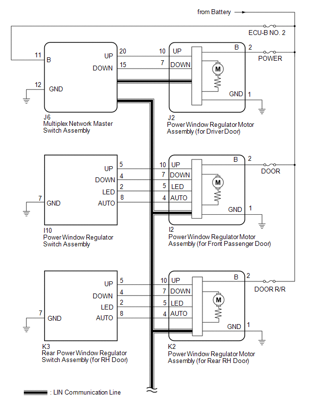
The power window regulator motor assemblies are operated by the multiplex network master switch assembly, power window regulator switch assembly or rear power window regulator switch assemblies. The power window regulator motor assemblies have motor, regulator and ECU functions.
This DTC is stored when a power window regulator motor assembly is malfunctioning, or the ECU built into the power window regulator motor assembly determines that the fully closed power window position has deviated approximately 20 mm (0.787 in.) or more from the normal position.
D-Door Motor|
DTC No. |
Detection Item |
DTC Detection Condition |
Trouble Area |
|---|---|---|---|
|
B2311 |
Power Window Motor Malfunction |
|
|
|
Vehicle Condition |
|||
|
Pattern 1 |
Pattern 2 |
||
|
Diagnosis Condition |
When the full closing operation |
- |
○ |
|
Malfunction Status |
Power window regulator motor assembly (for driver door) is malfunctioning |
○ |
- |
|
Window position has deviated approximately 20 mm (0.787 in.)or more from normal position |
- |
○ |
|
|
Detection Time |
- |
- |
|
|
Number of Trips |
1 trip |
1 trip |
|
HINT:
DTC will be output when conditions for either of the patterns in the table above are met.
P-Door Motor|
DTC No. |
Detection Item |
DTC Detection Condition |
Trouble Area |
|---|---|---|---|
|
B2311 |
Power Window Motor Malfunction |
|
|
|
Vehicle Condition |
|||
|
Pattern 1 |
Pattern 2 |
||
|
Diagnosis Condition |
When the full closing operation |
- |
○ |
|
Malfunction Status |
Power window regulator motor assembly (for front passenger door) is malfunctioning |
○ |
- |
|
Window position has deviated approximately 20 mm (0.787 in.)or more from normal position |
- |
○ |
|
|
Detection Time |
- |
- |
|
|
Number of Trips |
1 trip |
1 trip |
|
HINT:
DTC will be output when conditions for either of the patterns in the table above are met.
RL-Door Motor|
DTC No. |
Detection Item |
DTC Detection Condition |
Trouble Area |
|---|---|---|---|
|
B2311 |
Power Window Motor Malfunction |
|
|
|
Vehicle Condition |
|||
|
Pattern 1 |
Pattern 2 |
||
|
Diagnosis Condition |
When the full closing operation |
- |
○ |
|
Malfunction Status |
Power window regulator motor assembly (for rear LH door) is malfunctioning |
○ |
- |
|
Window position has deviated approximately 20 mm (0.787 in.)or more from normal position |
- |
○ |
|
|
Detection Time |
- |
- |
|
|
Number of Trips |
1 trip |
1 trip |
|
HINT:
DTC will be output when conditions for either of the patterns in the table above are met.
RR-Door Motor|
DTC No. |
Detection Item |
DTC Detection Condition |
Trouble Area |
|---|---|---|---|
|
B2311 |
Power Window Motor Malfunction |
|
|
|
Vehicle Condition |
|||
|
Pattern 1 |
Pattern 2 |
||
|
Diagnosis Condition |
When the full closing operation |
- |
○ |
|
Malfunction Status |
Power window regulator motor assembly (for rear RH door) is malfunctioning |
○ |
- |
|
Window position has deviated approximately 20 mm (0.787 in.)or more from normal position |
- |
○ |
|
|
Detection Time |
- |
- |
|
|
Number of Trips |
1 trip |
1 trip |
|
HINT:
DTC will be output when conditions for either of the patterns in the table above are met.
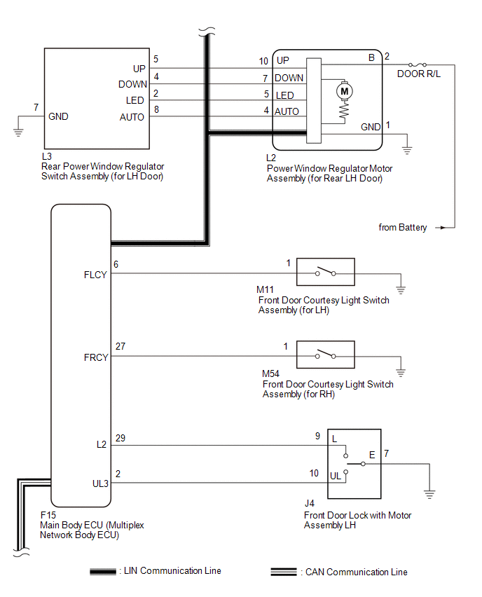
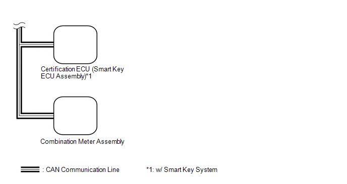
WIRING DIAGRAM
CAUTION / NOTICE / HINT
NOTICE:
- DTC B2311 is stored in each power window regulator motor assembly.
- If a power window regulator motor assembly has been replaced with a
new one, initialize the power window control system.
Click here
.gif)
- If a power window regulator motor assembly and door window regulator
sub-assembly have been removed and installed, or if a power window regulator
motor assembly was reused when a door glass or door glass run was replaced,
initialize the power window control system.
Click here
- Inspect the fuses for circuits related to this system before performing the following procedure.
- The power window control system uses the LIN communication system. Inspect
the communication function by following How to Proceed with Troubleshooting.
Troubleshoot the power window control system after confirming that the communication
system is functioning properly.
Click here
PROCEDURE
|
1. |
CHECK FOR DTC |
(a) Clear the DTCs.
Click here
(b) Check for DTCs.
Click here
OK:
DTC B2311 is not output.
| OK | .gif) |
USE SIMULATION METHOD TO CHECK
|
|
.gif)
|
2. |
CHECK DTC OUTPUT |
(a) Check the parts from which this DTC has been output.
|
Result |
Proceed to |
|---|---|
|
DTC output from power window regulator motor assembly (for driver door) |
A |
|
DTC output from power window regulator motor assembly (for front passenger door) |
B |
|
DTC output from power window regulator motor assembly (for rear LH door) |
C |
|
DTC output from power window regulator motor assembly (for rear RH door) |
D |
| B | |
GO TO STEP 4 |
| C | |
GO TO STEP 5 |
| D | |
GO TO STEP 6 |
|
|
3. |
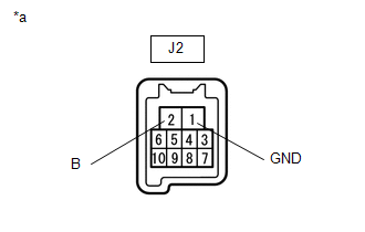
CHECK HARNESS AND CONNECTOR (POWER WINDOW REGULATOR MOTOR ASSEMBLY (FOR DRIVER DOOR) - BATTERY AND BODY GROUND) |
|
(a) Measure the voltage according to the value(s) in the table below. Standard Voltage:
|
|
(b) Measure the resistance according to the value(s) in the table below.
Standard Resistance:
|
Tester Connection |
Condition |
Specified Condition |
|---|---|---|
|
J2-1 (GND) - Body ground |
Always |
Below 1 Ω |
| OK | |
GO TO STEP 7 |
| NG | |
REPAIR OR REPLACE HARNESS OR CONNECTOR |
|
4. |
CHECK HARNESS AND CONNECTOR (POWER WINDOW REGULATOR MOTOR ASSEMBLY (FOR FRONT PASSENGER DOOR) - BATTERY AND BODY GROUND) |
|
(a) Measure the voltage according to the value(s) in the table below. Standard Voltage:
|
|

(b) Measure the resistance according to the value(s) in the table below.
Standard Resistance:
|
Tester Connection |
Condition |
Specified Condition |
|---|---|---|
|
I2-1 (GND) - Body ground |
Always |
Below 1 Ω |
| OK | |
GO TO STEP 7 |
| NG | |
REPAIR OR REPLACE HARNESS OR CONNECTOR |
|
5. |
CHECK HARNESS AND CONNECTOR (POWER WINDOW REGULATOR MOTOR ASSEMBLY (FOR REAR LH DOOR) - BATTERY AND BODY GROUND) |
|
(a) Measure the voltage according to the value(s) in the table below. Standard Voltage:
|
|
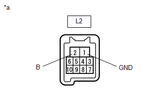
(b) Measure the resistance according to the value(s) in the table below.
Standard Resistance:
|
Tester Connection |
Condition |
Specified Condition |
|---|---|---|
|
L2-1 (GND) - Body ground |
Always |
Below 1 Ω |
| OK | |
GO TO STEP 7 |
| NG | |
REPAIR OR REPLACE HARNESS OR CONNECTOR |
|
6. |
CHECK HARNESS AND CONNECTOR (POWER WINDOW REGULATOR MOTOR ASSEMBLY (FOR REAR RH DOOR) - BATTERY AND BODY GROUND) |
|
(a) Measure the voltage according to the value(s) in the table below. Standard Voltage:
|
|
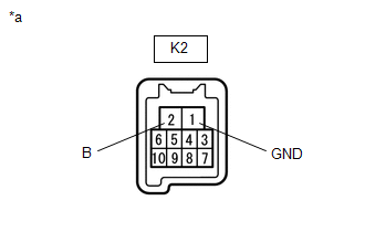
(b) Measure the resistance according to the value(s) in the table below.
Standard Resistance:
|
Tester Connection |
Condition |
Specified Condition |
|---|---|---|
|
K2-1 (GND) - Body ground |
Always |
Below 1 Ω |
| NG | |
REPAIR OR REPLACE HARNESS OR CONNECTOR |
|
|
7. |
PERFORM ACTIVE TEST USING TECHSTREAM (APPLICABLE LOCATION) |
(a) Connect the Techstream to the DLC3.
(b) Turn the ignition switch to ON.
(c) Turn the Techstream on.
(d) Enter the following menus: Body Electrical / (desired system) / Active Test.
HINT:
Perform the Active Test for the power window regulator motor assembly that has DTC B2311 stored in its ECU.
(e) Perform the Active Test according to the display on the Techstream.
CAUTION:
Be careful to avoid injuries as this test causes vehicle parts to move. During the Active Test, the jam protection function will not operate.
.png) Body Electrical > D-Door Motor
> Active Test
Body Electrical > D-Door Motor
> Active Test
|
Tester Display |
Measurement Item |
Control Range |
Diagnostic Note |
|---|---|---|---|
|
Power Window |
Power window |
OFF / DOWN / UP |
- |
|
Tester Display |
Measurement Item |
Control Range |
Diagnostic Note |
|---|---|---|---|
|
Power Window |
Power window |
OFF / DOWN / UP |
- |
|
Tester Display |
Measurement Item |
Control Range |
Diagnostic Note |
|---|---|---|---|
|
Power Window |
Power window |
OFF / DOWN / UP |
- |
|
Tester Display |
Measurement Item |
Control Range |
Diagnostic Note |
|---|---|---|---|
|
Power Window |
Power window |
OFF / DOWN / UP |
- |
|
Tester Display |
|---|
|
Power Window |
|
Tester Display |
|---|
|
Power Window |
|
Tester Display |
|---|
|
Power Window |
|
Tester Display |
|---|
|
Power Window |
OK:
Each power window operates normally.
|
Result |
Proceed to |
|---|---|
|
OK |
A |
|
NG (Driver door power window) |
B |
|
NG (Front passenger door power window) |
|
|
NG (Rear LH door power window) |
C |
|
NG (Rear RH door power window) |
| B | |
REPLACE POWER WINDOW REGULATOR MOTOR ASSEMBLY (FOR DRIVER DOOR OR FRONT PASSENGER DOOR) |
| C | |
REPLACE POWER WINDOW REGULATOR MOTOR ASSEMBLY (FOR REAR LH DOOR OR REAR RH DOOR) |
|
|
8. |
PERFORM INITIALIZATION (APPLICABLE LOCATION) |
(a) Initialize the power window regulator motor assembly.
Click here
HINT:
Initialize the power window regulator motor assembly that has DTC B2311 stored in its ECU.
|
|
9. |
CHECK POWER WINDOW CONTROL SYSTEM (APPLICABLE LOCATION) |
(a) Check that the power window operates normally by opening and closing it.
Click here
HINT:
Check the power window operation of the window where DTC B2311 has been stored.
OK:
Each power window operates normally.
|
Result |
Proceed to |
|---|---|
|
OK |
A |
|
NG (Driver door power window) |
B |
|
NG (Front passenger door power window) |
|
|
NG (Rear LH door power window) |
C |
|
NG (Rear RH door power window) |
| B | |
REPLACE POWER WINDOW REGULATOR MOTOR ASSEMBLY (FOR DRIVER DOOR OR FRONT PASSENGER DOOR) |
| C | |
REPLACE POWER WINDOW REGULATOR MOTOR ASSEMBLY (FOR REAR LH DOOR OR REAR RH DOOR) |
|
|
10. |
CHECK WHETHER PARTS HAVE BEEN INSTALLED CORRECTLY |
(a) Check that the power window components are installed correctly.
OK:
Power window components are installed correctly.
| NG | |
INSTALL PARTS CORRECTLY |
|
|
11. |
CHECK DTC OUTPUT |
(a) Turn the ignition switch to off.
(b) Wait for at least 10 seconds, and then turn the ignition switch to ON.
(c) Check for DTCs.
Click here
OK:
B2311 is not output.
|
Result |
Proceed to |
|---|---|
|
OK |
A |
|
NG (Driver door power window) |
B |
|
NG (Front passenger door power window) |
|
|
NG (Rear LH door power window) |
C |
|
NG (Rear RH door power window) |
| A | |
END |
| B | |
REPLACE POWER WINDOW REGULATOR MOTOR ASSEMBLY (FOR DRIVER DOOR OR FRONT PASSENGER DOOR) |
| C | |
REPLACE POWER WINDOW REGULATOR MOTOR ASSEMBLY (FOR REAR LH DOOR OR REAR RH DOOR) |
 Operation History List
OPERATION HISTORY LIST
NOTICE:
If the vehicle or vehicle controls are operated (for example, during
initial inspection when the vehicle is brought in for repair) before operation
his ...
 Power Window Switch Malfunction (B2312)
DESCRIPTION
The power window regulator motor assemblies are operated by the multiplex network
master switch assembly, power window regulator switch assembly or rear power window
regulator switch ...
Other materials:
Toyota CH-R Service Manual > Continuously Variable Transaxle System: Torque Converter Clutch Pressure Control Solenoid Control Circuit Electrical
(P2759)
DESCRIPTION
The ECM uses the shift solenoid valve SLU to perform forward and reverse clutch
control or lock-up clutch control.
*1
Spool Valve
*2
Sleeve
*3
Solenoid Coil
-
-
*a
...
Toyota CH-R Service Manual > Navigation System: Parts Location
PARTS LOCATION
ILLUSTRATION
*1
MAP LIGHT ASSEMBLY (TELEPHONE MICROPHONE ASSEMBLY)
*2
SKID CONTROL ECU (BRAKE ACTUATOR ASSEMBLY)
*3
NO. 1 ENGINE ROOM RELAY BLOCK
- DCM/MAYDAY FUSE
*4
PARK/NEUTRAL POSI ...
Toyota C-HR (AX20) 2023-2026 Owner's Manual
Toyota CH-R Owners Manual
- For safety and security
- Instrument cluster
- Operation of each component
- Driving
- Interior features
- Maintenance and care
- When trouble arises
- Vehicle specifications
- For owners
Toyota CH-R Service Manual
- Introduction
- Maintenance
- Audio / Video
- Cellular Communication
- Navigation / Multi Info Display
- Park Assist / Monitoring
- Brake (front)
- Brake (rear)
- Brake Control / Dynamic Control Systems
- Brake System (other)
- Parking Brake
- Axle And Differential
- Drive Shaft / Propeller Shaft
- K114 Cvt
- 3zr-fae Battery / Charging
- Networking
- Power Distribution
- Power Assist Systems
- Steering Column
- Steering Gear / Linkage
- Alignment / Handling Diagnosis
- Front Suspension
- Rear Suspension
- Tire / Wheel
- Tire Pressure Monitoring
- Door / Hatch
- Exterior Panels / Trim
- Horn
- Lighting (ext)
- Mirror (ext)
- Window / Glass
- Wiper / Washer
- Door Lock
- Heating / Air Conditioning
- Interior Panels / Trim
- Lighting (int)
- Meter / Gauge / Display
- Mirror (int)
- Power Outlets (int)
- Pre-collision
- Seat
- Seat Belt
- Supplemental Restraint Systems
- Theft Deterrent / Keyless Entry

0.0095