Toyota CH-R Service Manual: Parts Location
PARTS LOCATION
ILLUSTRATION
|
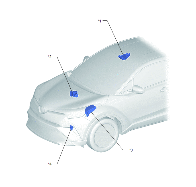
*1 |
MAP LIGHT ASSEMBLY (TELEPHONE MICROPHONE ASSEMBLY) |
*2 |
SKID CONTROL ECU (BRAKE ACTUATOR ASSEMBLY) |
|
*3 |
NO. 1 ENGINE ROOM RELAY BLOCK - DCM/MAYDAY FUSE |
*4 |
PARK/NEUTRAL POSITION SWITCH |
ILLUSTRATION
|
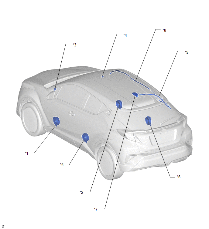
*1 |
FRONT NO. 1 SPEAKER ASSEMBLY LH |
*2 |
FRONT NO. 1 SPEAKER ASSEMBLY RH |
|
*3 |
FRONT NO. 2 SPEAKER ASSEMBLY LH |
*4 |
FRONT NO. 2 SPEAKER ASSEMBLY RH |
|
*5 |
REAR SPEAKER ASSEMBLY LH |
*6 |
REAR SPEAKER ASSEMBLY RH |
|
*7 |
ROOF ANTENNA ASSEMBLY - SiriusXM - FM - AM |
*8 |
NO. 2 ANTENNA CORD SUB-ASSEMBLY |
|
*9 |
NO. 3 ANTENNA CORD SUB-ASSEMBLY |
- |
- |
ILLUSTRATION
|
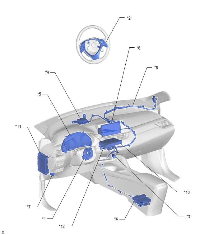
*1 |
SPIRAL CABLE WITH SENSOR SUB-ASSEMBLY |
*2 |
STEERING PAD SWITCH ASSEMBLY |
|
*3 |
NO. 1 STEREO JACK ADAPTER ASSEMBLY |
*4 |
DCM (TELEMATICS TRANSCEIVER) |
|
*5 |
COMBINATION METER ASSEMBLY |
*6 |
ANTENNA CORD SUB-ASSEMBLY |
|
*7 |
DLC3 |
*8 |
RADIO AND DISPLAY RECEIVER ASSEMBLY |
|
*9 |
NAVIGATION ANTENNA ASSEMBLY - GPS |
*10 |
NAVIGATION ECU |
|
*11 |
INSTRUMENT PANEL JUNCTION BLOCK ASSEMBLY - ECU-ACC FUSE - RADIO FUSE - PANEL FUSE - ECU-B NO. 2 FUSE - ECU-IG1 NO. 4 FUSE - ECU-IG2 NO. 3 FUSE |
*12 |
NO. 1 NAVIGATION WIRE |
 Precaution
PRECAUTION
PRECAUTION FOR NAVIGATION SYSTEM
NOTICE:
When replacing the radio and display receiver assembly or navigation
ECU, always replace it with a new one. If a radio and display re ...
 System Diagram
SYSTEM DIAGRAM
...
Other materials:
Toyota CH-R Service Manual > Electric Parking Brake Actuator: Installation
INSTALLATION
CAUTION / NOTICE / HINT
HINT:
Use the same procedure for the RH side and LH side.
The following procedure is for the LH side.
PROCEDURE
1. INSTALL PARKING BRAKE ACTUATOR ASSEMBLY
(a) Apply a light coat of lithium soap base glycol grease to a new O-ring.
(b) Inst ...
Toyota CH-R Service Manual > Rear Seat Outer Belt Assembly: Installation
INSTALLATION
CAUTION / NOTICE / HINT
HINT:
Use the same procedure for the RH side and LH side.
The procedure listed below is for the LH side.
PROCEDURE
1. INSPECT REAR SEAT 3 POINT TYPE OUTER BELT ASSEMBLY
Click here
2. INSTALL REAR SEAT 3 POINT TYPE OUTER BELT ASSEMBLY LH ...
Toyota C-HR (AX20) 2023-2026 Owner's Manual
Toyota CH-R Owners Manual
- For safety and security
- Instrument cluster
- Operation of each component
- Driving
- Interior features
- Maintenance and care
- When trouble arises
- Vehicle specifications
- For owners
Toyota CH-R Service Manual
- Introduction
- Maintenance
- Audio / Video
- Cellular Communication
- Navigation / Multi Info Display
- Park Assist / Monitoring
- Brake (front)
- Brake (rear)
- Brake Control / Dynamic Control Systems
- Brake System (other)
- Parking Brake
- Axle And Differential
- Drive Shaft / Propeller Shaft
- K114 Cvt
- 3zr-fae Battery / Charging
- Networking
- Power Distribution
- Power Assist Systems
- Steering Column
- Steering Gear / Linkage
- Alignment / Handling Diagnosis
- Front Suspension
- Rear Suspension
- Tire / Wheel
- Tire Pressure Monitoring
- Door / Hatch
- Exterior Panels / Trim
- Horn
- Lighting (ext)
- Mirror (ext)
- Window / Glass
- Wiper / Washer
- Door Lock
- Heating / Air Conditioning
- Interior Panels / Trim
- Lighting (int)
- Meter / Gauge / Display
- Mirror (int)
- Power Outlets (int)
- Pre-collision
- Seat
- Seat Belt
- Supplemental Restraint Systems
- Theft Deterrent / Keyless Entry

0.0097