Toyota CH-R Service Manual: Removal
REMOVAL
CAUTION / NOTICE / HINT
The necessary procedures (adjustment, calibration, initialization, or registration) that must be performed after parts are removed, installed, or replaced during the combination meter removal/installation are shown below.
Necessary Procedure After Parts Removed/Installed/Replaced|
Replacement Part or Procedure |
Necessary Procedures |
Effects/Inoperative when not performed |
Link |
|---|---|---|---|
|
Disconnect cable from negative battery terminal |
Initialize back door lock |
Power door lock control system |
|
|
Memorize steering angle neutral point |
Lane departure alert system (w/ Steering Control) |
|
|
|
Pre-collision system |
PROCEDURE
1. PRECAUTION
NOTICE:
After turning the ignition switch off, waiting time may be required before disconnecting the cable from the negative (-) battery terminal. Therefore, make sure to read the disconnecting the cable from the negative (-) battery terminal notices before proceeding with work.
Click here .gif)
2. DISCONNECT CABLE FROM NEGATIVE BATTERY TERMINAL
Click here
NOTICE:
When disconnecting the cable, some systems need to be initialized after the cable is reconnected.
Click here
3. REMOVE INSTRUMENT CLUSTER FINISH PANEL SUB-ASSEMBLY
Click here
4. REMOVE INSTRUMENT CLUSTER FINISH PANEL GARNISH ASSEMBLY
Click here
5. REMOVE INSTRUMENT CLUSTER FINISH PANEL ASSEMBLY
Click here
6. REMOVE NO. 2 INSTRUMENT PANEL GARNISH SUB-ASSEMBLY
Click here
7. REMOVE COMBINATION METER ASSEMBLY
|
(a) Remove the 2 screws. |
|
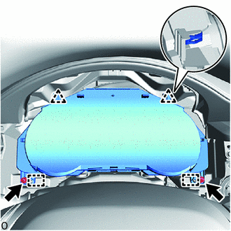
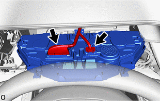
(b) Disengage the clips and guides.
|
(c) Disconnect the 2 connectors to remove the combination meter assembly. |
|
 Disassembly
DISASSEMBLY
CAUTION / NOTICE / HINT
NOTICE:
When removing and installing the combination meter glass, make sure
not to touch the display panel.
Do not allow any dirt (fingerprints, ...
 Reassembly
REASSEMBLY
CAUTION / NOTICE / HINT
NOTICE:
When removing and installing the combination meter glass, make sure
not to touch the display panel.
Do not allow any dirt (fingerprints, g ...
Other materials:
Toyota CH-R Service Manual > Front Wiper Motor: Removal
REMOVAL
CAUTION / NOTICE / HINT
NOTICE:
Make sure to hold the front wiper arm while lifting it as lifting the front wiper
arm by the front wiper blade may damage or deform the front wiper blade.
PROCEDURE
1. REMOVE FRONT WIPER ARM HEAD CAP
(a) Using a screwdriver with its tip wrapped in prot ...
Toyota CH-R Service Manual > Can Communication System: Open in Bus 4 Main Bus Line
DESCRIPTION
There may be an open circuit in one of the CAN main bus lines when the resistance
between terminals 22 (CA2H) and 7 (CA2L) of the central gateway ECU (network gateway
ECU) is 70 Ω or higher.
Symptom
Trouble Area
Resistance between terminals 2 ...
Toyota C-HR (AX20) 2023-2026 Owner's Manual
Toyota CH-R Owners Manual
- For safety and security
- Instrument cluster
- Operation of each component
- Driving
- Interior features
- Maintenance and care
- When trouble arises
- Vehicle specifications
- For owners
Toyota CH-R Service Manual
- Introduction
- Maintenance
- Audio / Video
- Cellular Communication
- Navigation / Multi Info Display
- Park Assist / Monitoring
- Brake (front)
- Brake (rear)
- Brake Control / Dynamic Control Systems
- Brake System (other)
- Parking Brake
- Axle And Differential
- Drive Shaft / Propeller Shaft
- K114 Cvt
- 3zr-fae Battery / Charging
- Networking
- Power Distribution
- Power Assist Systems
- Steering Column
- Steering Gear / Linkage
- Alignment / Handling Diagnosis
- Front Suspension
- Rear Suspension
- Tire / Wheel
- Tire Pressure Monitoring
- Door / Hatch
- Exterior Panels / Trim
- Horn
- Lighting (ext)
- Mirror (ext)
- Window / Glass
- Wiper / Washer
- Door Lock
- Heating / Air Conditioning
- Interior Panels / Trim
- Lighting (int)
- Meter / Gauge / Display
- Mirror (int)
- Power Outlets (int)
- Pre-collision
- Seat
- Seat Belt
- Supplemental Restraint Systems
- Theft Deterrent / Keyless Entry

0.0076