Toyota CH-R Service Manual: Front Power Seat Control System
Parts Location
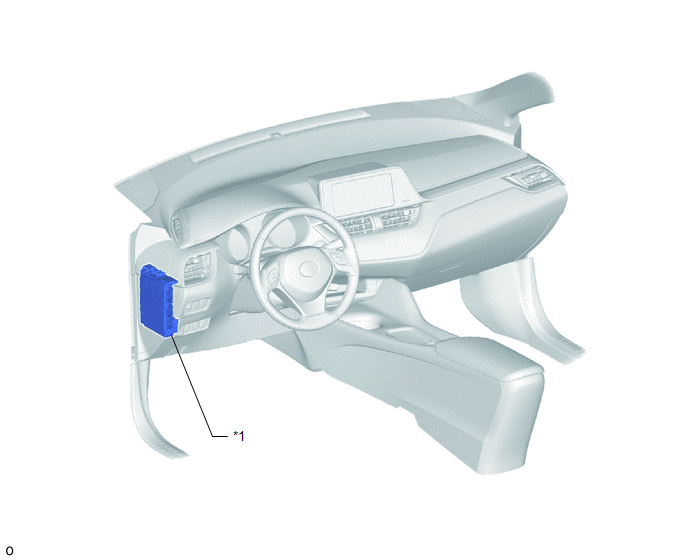
PARTS LOCATION
ILLUSTRATION
|
*1 |
INSTRUMENT PANEL JUNCTION BLOCK ASSEMBLY - P/SEAT FUSE |
- |
- |
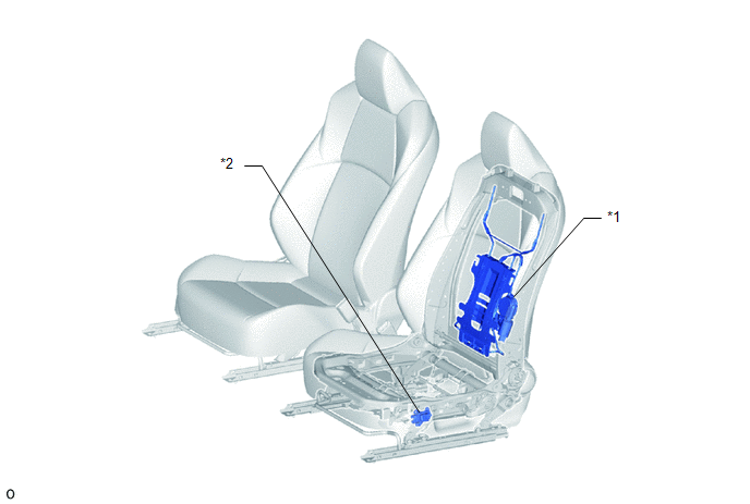
ILLUSTRATION
|
*1 |
LUMBAR SUPPORT ADJUSTER ASSEMBLY LH |
*2 |
FRONT LUMBAR POWER SEAT SWITCH |
System Diagram
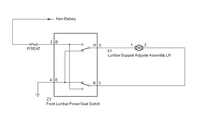
SYSTEM DIAGRAM
Operation Check
OPERATION CHECK
CHECK POWER SEAT FUNCTION
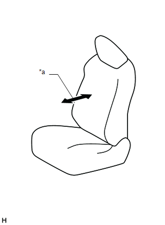
(a) Check the basic functions.
|
*a |
Lumbar Support Adjustment Function |
(1) Operate the front lumber power seat switch and check the lumbar support adjustment function operates properly:
CHECK LUMBAR SUPPORT ADJUSTMENT MOTOR
(a) Check the PTC operation inside the lumbar support adjustment motor.
NOTICE:
The inspection should be performed with the seat installed to the vehicle.
(1) Operate the front lumbar power seat switch and move the lumbar support to either the foremost or rearmost position. Keep the seat in that position for approximately 60 seconds.
(2) Operate the front lumbar power seat switch again and continue to try to move the lumbar support in the same direction as in the previous step. Measure the time until the current is shut off (motor operation sound stops).
Standard:
4 to 90 seconds
(3) After the current is shut off, release the front lumbar power seat switch and wait for approximately 60 seconds.
(4) Operate the front lumbar power seat switch and move the lumbar support in the opposite direction. Check that the motor operates.
Problem Symptoms Table
PROBLEM SYMPTOMS TABLE
HINT:
- Use the table below to help determine the cause of problem symptoms. If multiple suspected areas are listed, the potential causes of the symptoms are listed in order of probability in the "Suspected Area" column of the table. Check each symptom by checking the suspected areas in the order they are listed. Replace parts as necessary.
- Inspect the fuses and relays related to this system before inspecting the suspected areas below.
|
Symptom |
Suspected Area |
Link |
|---|---|---|
|
Lumbar support adjustment function does not operate |
Front lumbar power seat switch |
|
|
Lumbar support adjuster assembly LH |
|
|
|
Wire harness or connector |
- |
.gif)
 Seat
Seat
...

Other materials:
Toyota CH-R Service Manual > Center Airbag Sensor Assembly: Components
COMPONENTS
ILLUSTRATION
*A
w/ Rear Air Duct
-
-
*1
AIRBAG SENSOR ASSEMBLY
*2
REAR NO. 2 AIR DUCT
Tightening torque for "Major areas involving basic vehicle performance
...
Toyota CH-R Service Manual > Navigation System: Mute Signal Circuit between Radio Receiver and Telematics Transceiver
DESCRIPTION
The telematics transceiver sends a mute signal to the radio and display receiver
assembly.
The radio and display receiver assembly controls the volume according to the
mute signal from the telematics transceiver.
WIRING DIAGRAM
CAUTION / NOTICE / HINT
NOTICE:
Depending on the ...
Toyota C-HR (AX20) 2023-2026 Owner's Manual
Toyota CH-R Owners Manual
- For safety and security
- Instrument cluster
- Operation of each component
- Driving
- Interior features
- Maintenance and care
- When trouble arises
- Vehicle specifications
- For owners
Toyota CH-R Service Manual
- Introduction
- Maintenance
- Audio / Video
- Cellular Communication
- Navigation / Multi Info Display
- Park Assist / Monitoring
- Brake (front)
- Brake (rear)
- Brake Control / Dynamic Control Systems
- Brake System (other)
- Parking Brake
- Axle And Differential
- Drive Shaft / Propeller Shaft
- K114 Cvt
- 3zr-fae Battery / Charging
- Networking
- Power Distribution
- Power Assist Systems
- Steering Column
- Steering Gear / Linkage
- Alignment / Handling Diagnosis
- Front Suspension
- Rear Suspension
- Tire / Wheel
- Tire Pressure Monitoring
- Door / Hatch
- Exterior Panels / Trim
- Horn
- Lighting (ext)
- Mirror (ext)
- Window / Glass
- Wiper / Washer
- Door Lock
- Heating / Air Conditioning
- Interior Panels / Trim
- Lighting (int)
- Meter / Gauge / Display
- Mirror (int)
- Power Outlets (int)
- Pre-collision
- Seat
- Seat Belt
- Supplemental Restraint Systems
- Theft Deterrent / Keyless Entry

0.0066