Toyota CH-R Service Manual: Engine Hood Courtesy Switch Circuit
DESCRIPTION
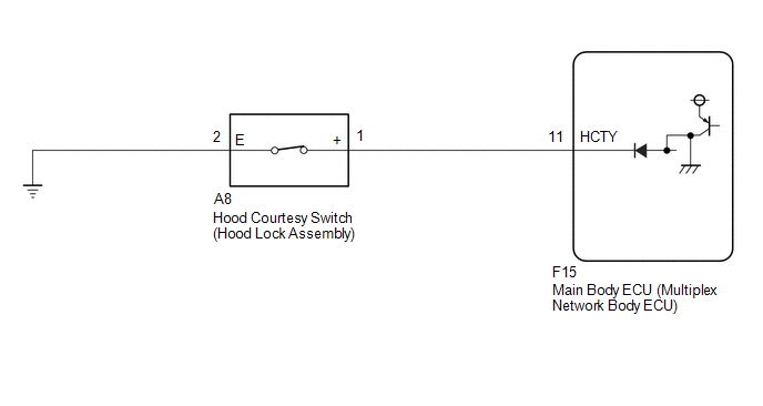
The hood courtesy switch is built into the hood lock assembly. This switch turns on when the hood is closed and turns off when the hood is opened.
WIRING DIAGRAM
CAUTION / NOTICE / HINT
NOTICE:
Before replacing the main body ECU (multiplex network body ECU), refer to REGISTRATION.*1
Click here .gif)
- *1: w/ Smart Key System
PROCEDURE
|
1. |
READ VALUE USING TECHSTREAM (HOOD COURTESY SW) |
(a) Connect the Techstream to the DLC3.
(b) Turn the ignition switch to ON.
(c) Turn the Techstream on.
(d) Enter the following menus: Body Electrical / Main Body / Data List.
(e) Read the Data List according to the display on the Techstream.
Body Electrical > Main Body > Data List|
Tester Display |
Measurement Item |
Range |
Normal Condition |
Diagnostic Note |
|---|---|---|---|---|
|
Hood Courtesy SW |
Hood courtesy switch |
ON or OFF |
ON: Hood open OFF: Hood closed |
- |
|
Tester Display |
|---|
|
Hood Courtesy SW |
OK:
The Techstream display changes correctly in response to the hood courtesy switch (hood lock assembly) status.
| OK | .gif) |
REPLACE MAIN BODY ECU (MULTIPLEX NETWORK BODY ECU) |
|
.gif)
|
2. |
INSPECT HOOD COURTESY SWITCH (HOOD LOCK ASSEMBLY) |
(a) Remove the hood courtesy switch (hood lock assembly).
Click here
(b) Inspect the hood courtesy switch (hood lock assembly).
Click here
| NG | |
REPLACE HOOD COURTESY SWITCH (HOOD LOCK ASSEMBLY) |
|
|
3. |
CHECK HARNESS AND CONNECTOR (MAIN BODY ECU (MULTIPLEX NETWORK BODY ECU) - HOOD COURTESY SWITCH (HOOD LOCK ASSEMBLY) - BODY GROUND) |
(a) Disconnect the F15 main body ECU (multiplex network body ECU) connector.
(b) Disconnect the A8 hood courtesy switch (hood lock assembly) connector.
(c) Measure the resistance according to the value(s) in the table below.
Standard Resistance:
|
Tester Connection |
Condition |
Specified Condition |
|---|---|---|
|
F15-11 (HCTY) - A8-1 (+) |
Always |
Below 1 Ω |
|
F15-11 (HCTY) or A8-1 (+) - Body ground |
Always |
10 kΩ or higher |
|
A8-2 (E) - Body ground |
Always |
Below 1 Ω |
| OK | |
REPLACE MAIN BODY ECU (MULTIPLEX NETWORK BODY ECU) |
| NG | |
REPAIR OR REPLACE HARNESS OR CONNECTOR |
 Operation History List
OPERATION HISTORY LIST
NOTICE:
If the vehicle or vehicle controls are operated (for example, during
initial inspection when the vehicle is brought in for repair) before operation
his ...
 Horn Circuit
DESCRIPTION
When the theft deterrent system is switched from the armed state to the alarm
sounding state, the main body ECU (multiplex network body ECU) transmits a signal
to cause the horns to s ...
Other materials:
Toyota CH-R Service Manual > Side Airbag Sensor(for Center Pillar): Removal
REMOVAL
CAUTION / NOTICE / HINT
The necessary procedures (adjustment, calibration, initialization, or registration)
that must be performed after parts are removed, installed, or replaced during the
side airbag sensor removal/installation are shown below.
Necessary Procedure After Parts Remove ...
Toyota CH-R Service Manual > 3zr-fae Battery: Components
COMPONENTS
ILLUSTRATION
*1
BATTERY
*2
NO. 2 BATTERY CLAMP
*3
POSITIVE BATTERY TERMINAL
*4
NEGATIVE BATTERY TERMINAL
*5
FUSIBLE LINK COVER
*6
BATTERY INS ...
Toyota C-HR (AX20) 2023-2026 Owner's Manual
Toyota CH-R Owners Manual
- For safety and security
- Instrument cluster
- Operation of each component
- Driving
- Interior features
- Maintenance and care
- When trouble arises
- Vehicle specifications
- For owners
Toyota CH-R Service Manual
- Introduction
- Maintenance
- Audio / Video
- Cellular Communication
- Navigation / Multi Info Display
- Park Assist / Monitoring
- Brake (front)
- Brake (rear)
- Brake Control / Dynamic Control Systems
- Brake System (other)
- Parking Brake
- Axle And Differential
- Drive Shaft / Propeller Shaft
- K114 Cvt
- 3zr-fae Battery / Charging
- Networking
- Power Distribution
- Power Assist Systems
- Steering Column
- Steering Gear / Linkage
- Alignment / Handling Diagnosis
- Front Suspension
- Rear Suspension
- Tire / Wheel
- Tire Pressure Monitoring
- Door / Hatch
- Exterior Panels / Trim
- Horn
- Lighting (ext)
- Mirror (ext)
- Window / Glass
- Wiper / Washer
- Door Lock
- Heating / Air Conditioning
- Interior Panels / Trim
- Lighting (int)
- Meter / Gauge / Display
- Mirror (int)
- Power Outlets (int)
- Pre-collision
- Seat
- Seat Belt
- Supplemental Restraint Systems
- Theft Deterrent / Keyless Entry

0.0079