Toyota CH-R Service Manual: DCM Data Signal Circuit between Navigation ECU and DCM
DESCRIPTION
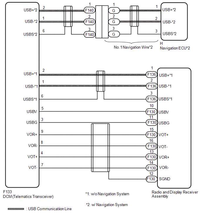
This circuit is used to send and receive signals between the DCM (Telematics Transceiver) and radio and display receiver assembly.
WIRING DIAGRAM
PROCEDURE
|
1. |
CHECK VEHICLE TYPE |
(a) Check vehicle type.
|
Result |
Proceed to |
|---|---|
|
w/ Navigation System |
A |
|
w/o Navigation System |
B |
| B | .gif) |
GO TO STEP 5 |
|
.gif)
|
2. |
CHECK HARNESS AND CONNECTOR (DCM (TELEMATICS TRANSCEIVER) - NO. 1 NAVIGATION WIRE) |
(a) Disconnect the F140 No. 1 Navigation Wire connector.
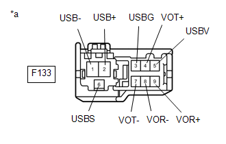
(b) Disconnect the F133 DCM (Telematics Transceiver) connector.
(c) Measure the resistance according to the value(s) in the table below.
Standard Resistance:
|
Tester Connection |
Condition |
Specified Condition |
|---|---|---|
|
F133-2 (USB+) - F140-1 |
Always |
Below 1 Ω |
|
F133-1 (USB-) -F140-2 |
Always |
Below 1 Ω |
|
F133-6 (USBS) - F140-3 |
Always |
Below 1 Ω |
|
F133-2 (USB+) or F140-1 - Body ground |
Always |
10 kΩ or higher |
|
F133-1 (USB-) or F140-2 - Body ground |
Always |
10 kΩ or higher |
|
F133-6 (USBS) or F140-3 - Body ground |
Always |
10 kΩ or higher |
| NG | |
REPLACE NO. 1 NAVIGATION WIRE |
|
|
3. |
INSPECT NAVIGATION WIRE |
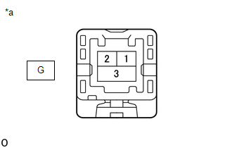
(a) Disconnect the G no. 1 navigation wire connector.
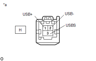
(b) Disconnect the H navigation ECU connector.
(c) Measure the resistance according to the value(s) in the table below.
Standard Resistance:
|
Tester Connection |
Condition |
Specified Condition |
|---|---|---|
|
G-1 -H-1 (USB+) |
Always |
Below 1 Ω |
|
G-2 - H-2 (USB-) |
Always |
Below 1 Ω |
|
G-3 - H-3 (USBS) |
Always |
Below 1 Ω |
|
G-1 or H-1 (USB+) - Body ground |
Always |
10 kΩ or higher |
|
G-2 or H-2 (USB-) - Body ground |
Always |
10 kΩ or higher |
|
G-3 or H-3 (USBS) - Body ground |
Always |
10 kΩ or higher |
|
*a |
Component without harness connected (No. 1 Navigation Wire) |
|
*a |
Component without harness connected (No. 1 Navigation Wire) |
| NG | |
REPAIR OR REPLACE HARNESS OR CONNECTOR |
|
|
4. |
CHECK HARNESS AND CONNECTOR (DCM (TELEMATICS TRANSCEIVER) - RADIO AND DISPLAY RECEIVER ASSEMBLY) |
(a) Disconnect the F133 DCM (Telematics Transceiver) connector.
(b) Disconnect the F130 radio and display receiver assembly connector.
(c) Measure the resistance according to the value(s) in the table below.
Standard Resistance:
|
Tester Connection |
Condition |
Specified Condition |
|---|---|---|
|
F133-5 (USBV) - F130-10 (USBV) |
Always |
Below 1 Ω |
|
F133-3 (USBG) - F130-11 (USBG) |
Always |
Below 1 Ω |
|
F133-9 (VOR+) - F130-15 (VOT+) |
Always |
Below 1 Ω |
|
F133-8 (VOR-) - F130-16 (VOT-) |
Always |
Below 1 Ω |
|
F133-4 (VOT+) - F130-13 (VOR+) |
Always |
Below 1 Ω |
|
F133-7 (VOT-) - F130-14 (VOR-) |
Always |
Below 1 Ω |
|
F133-5 (USBV) or F130-10 (USBV) - Body ground |
Always |
10 kΩ or higher |
|
F133-3 (USBG) or F130-11 (USBG) - Body ground |
Always |
10 kΩ or higher |
|
F133-9 (VOR+) or F130-15 (VOT+) - Body ground |
Always |
10 kΩ or higher |
|
F133-8 (VOR-) or F130-16 (VOT-) - Body ground |
Always |
10 kΩ or higher |
|
F133-4 (VOT+) or F130-13 (VOR+) - Body ground |
Always |
10 kΩ or higher |
|
F133-7 (VOT-) or F130-14 (VOR-) - Body ground |
Always |
10 kΩ or higher |
|
F130-12 (SGND) - Body ground |
Always |
10 kΩ or higher |
| OK | |
PROCEED TO NEXT SUSPECTED AREA SHOWN IN PROBLEM SYMPTOMS TABLE |
| NG | |
REPAIR OR REPLACE HARNESS OR CONNECTOR |
|
5. |
CHECK HARNESS AND CONNECTOR (DCM (TELEMATICS TRANSCEIVER) - RADIO AND DISPLAY RECEIVER ASSEMBLY) |
|
(a) Disconnect the F133 DCM (Telematics Transceiver) connector. |
|
|
(b) Disconnect the F130 and F136 radio and display receiver assembly connector. |
|
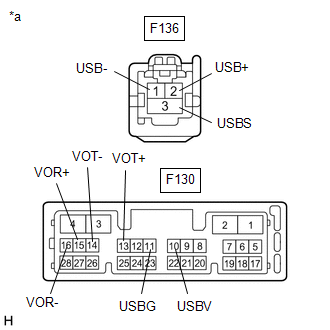
(c) Measure the resistance according to the value(s) in the table below.
Standard Resistance:
|
Tester Connection |
Condition |
Specified Condition |
|---|---|---|
|
F133-1 (USB-) - F136-2 (USB-) |
Always |
Below 1 Ω |
|
F133-2 (USB+) - F136-1 (USB+) |
Always |
Below 1 Ω |
|
F133-6 (USBS) - F136-3 (USBS) |
Always |
Below 1 Ω |
|
F133-3 (USBG) - F130-11 (USBG) |
Always |
Below 1 Ω |
|
F133-4 (VOT+) - F130-13 (VOR+) |
Always |
Below 1 Ω |
|
F133-5 (USBV) - F130-10 (USBV) |
Always |
Below 1 Ω |
|
F133-7 (VOT-) - F130-14 (VOR-) |
Always |
Below 1 Ω |
|
F133-8 (VOR-) - F130-16 (VOT-) |
Always |
Below 1 Ω |
|
F133-9 (VOR+) - F130-15 (VOT+) |
Always |
Below 1 Ω |
|
F133-1 (USB-) or F136-2 (USB-) - Body ground |
Always |
10 kΩ or higher |
|
F133-2 (USB+) or F136-1 (USB+) - Body ground |
Always |
10 kΩ or higher |
|
F133-6 (USBS) or F136-3 (USBS) - Body ground |
Always |
10 kΩ or higher |
|
F133-3 (USBG) or F130-11 (USBG) - Body ground |
Always |
10 kΩ or higher |
|
F133-4 (VOT+) or F130-13 (VOR+) - Body ground |
Always |
10 kΩ or higher |
|
F133-5 (USBV) or F130-10 (USBV) - Body ground |
Always |
10 kΩ or higher |
|
F133-7 (VOT-) or F130-14 (VOR-) - Body ground |
Always |
10 kΩ or higher |
|
F133-8 (VOR-) or F130-16 (VOT-) - Body ground |
Always |
10 kΩ or higher |
|
F133-9 (VOR+) or F130-15 (VOT+) - Body ground |
Always |
10 kΩ or higher |
| OK | |
PROCEED TO NEXT SUSPECTED AREA SHOWN IN PROBLEM SYMPTOMS TABLE |
| NG | |
REPAIR OR REPLACE HARNESS OR CONNECTOR |
 Does not Recognize Voice Commands Performed to Contact Support Center
PROCEDURE
1.
CHECK COMMUNICATION BASED VOICE RECOGNITION FUNCTION
(a) While paying attention to the condition of the spoken voice command, say
"Find a gas stat ...

Other materials:
Toyota CH-R Service Manual > Blind Spot Monitor System: Short to +B in Outer Mirror Indicator(Slave) (C1AB1)
DESCRIPTION
This DTC is stored when the blind spot monitor sensor RH (Slave) detects a short
to +B in the outer rear view mirror indicator RH.
DTC No.
Detection Item
DTC Detection Condition
Trouble Area
C1AB1
Short to +B in ...
Toyota CH-R Service Manual > Outer Mirror Switch: Components
COMPONENTS
ILLUSTRATION
*1
MULTIPLEX NETWORK MASTER SWITCH ASSEMBLY WITH FRONT ARMREST BASE UPPER
PANEL
*2
OUTER MIRROR SWITCH ASSEMBLY
...
Toyota C-HR (AX20) 2023-2026 Owner's Manual
Toyota CH-R Owners Manual
- For safety and security
- Instrument cluster
- Operation of each component
- Driving
- Interior features
- Maintenance and care
- When trouble arises
- Vehicle specifications
- For owners
Toyota CH-R Service Manual
- Introduction
- Maintenance
- Audio / Video
- Cellular Communication
- Navigation / Multi Info Display
- Park Assist / Monitoring
- Brake (front)
- Brake (rear)
- Brake Control / Dynamic Control Systems
- Brake System (other)
- Parking Brake
- Axle And Differential
- Drive Shaft / Propeller Shaft
- K114 Cvt
- 3zr-fae Battery / Charging
- Networking
- Power Distribution
- Power Assist Systems
- Steering Column
- Steering Gear / Linkage
- Alignment / Handling Diagnosis
- Front Suspension
- Rear Suspension
- Tire / Wheel
- Tire Pressure Monitoring
- Door / Hatch
- Exterior Panels / Trim
- Horn
- Lighting (ext)
- Mirror (ext)
- Window / Glass
- Wiper / Washer
- Door Lock
- Heating / Air Conditioning
- Interior Panels / Trim
- Lighting (int)
- Meter / Gauge / Display
- Mirror (int)
- Power Outlets (int)
- Pre-collision
- Seat
- Seat Belt
- Supplemental Restraint Systems
- Theft Deterrent / Keyless Entry

0.0079