Toyota CH-R Service Manual: SRS Warning Light Remains ON
DESCRIPTION
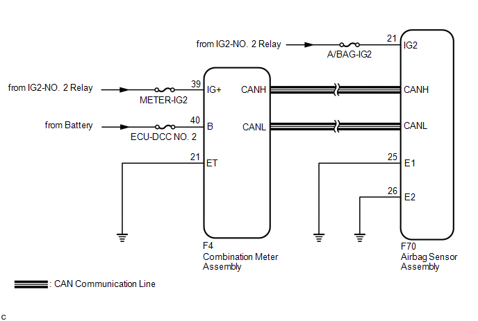
The SRS warning light is located in the combination meter assembly.
When the SRS is normal, the SRS warning light comes on for approximately 6 seconds after the ignition switch is turned from off to ON, and then goes off automatically.
If there is a malfunction in the SRS, the SRS warning light comes on to inform the driver of a problem.
If a malfunction occurs in the airbag sensor assembly, combination meter assembly or wire harness connected to the airbag sensor assembly or combination meter assembly, the SRS warning light comes on.
When terminals TC and CG of the DLC3 are connected, DTCs are displayed by blinking of the SRS warning light.
The SRS is equipped with a voltage-increase circuit (DC-DC converter) in the airbag sensor assembly in case the source voltage drops.
When the battery voltage drops, the voltage-increase circuit (DC-DC converter) functions to increase the voltage of the SRS to normal voltage. In addition, when the voltage drops, the SRS warning light will illuminate.
A malfunction in this circuit is not stored in the airbag sensor assembly. The SRS warning light automatically goes off when the source voltage returns to normal.
The signal to illuminate the SRS warning light is transmitted from the airbag sensor assembly to the combination meter assembly via CAN communication.
WIRING DIAGRAM
CAUTION / NOTICE / HINT
NOTICE:
- After turning the ignition switch off, waiting time may be required
before disconnecting the cable from the negative (-) battery terminal. Therefore,
make sure to read the disconnecting the cable from the negative (-) battery
terminal notices before proceeding with work.
Click here
.gif)
- Inspect the fuses for circuits related to this system before performing the following procedure.
- When replacing the combination meter assembly, always replace it with a new one. If a combination meter assembly which was installed to another vehicle is used, the information stored in it will not match the information from the vehicle and a DTC may be stored.
PROCEDURE
|
1. |
CHECK SRS WARNING LIGHT OPERATION |
(a) Turn the ignition switch ON and check the SRS warning light condition.
HINT:
The primary check is performed for approximately 6 seconds after the ignition switch is turned ON.
|
Result |
Proceed to |
|---|---|
|
After the primary check period, the SRS warning light remains on. |
A |
|
After the primary check period, the SRS warning light goes off and comes on again. |
B |
| B | .gif) |
GO TO STEP 6 |
|
.gif)
|
2. |
CHECK BATTERY VOLTAGE |
(a) Measure the voltage of the battery.
Standard Voltage:
11 to 14 V
| NG | |
INSPECT CHARGING SYSTEM AND BATTERY |
|
|
3. |
CHECK CONNECTOR |
(a) Turn the ignition switch off.
(b) Disconnect the cable from the negative (-) battery terminal.
CAUTION:
Wait at least 90 seconds after disconnecting the cable from the negative (-) battery terminal to disable the SRS system.
(c) Check that the connector is properly connected to the airbag sensor assembly.
OK:
The connector is properly connected.
HINT:
If the connector is not properly connected, reconnect the connector and proceed to the next inspection.
(d) Disconnect the connector from the airbag sensor assembly.
(e) Check that the terminals of the connector are not deformed or damaged.
OK:
The terminals are not deformed or damaged.
| NG | |
REPLACE WIRE HARNESS |
|
|
4. |
CHECK WIRE HARNESS (AIRBAG SENSOR ASSEMBLY - BODY GROUND) |
|
(a) Connect the cable to the negative (-) battery terminal. |
|
(b) Turn the ignition switch ON.
(c) Operate all components of the electrical systems (defogger, wipers, headlights, heater blower, etc.).
(d) Measure the voltage according to the value(s) in the table below.
Standard Voltage:
|
Tester Connection |
Switch Condition |
Specified Condition |
|---|---|---|
|
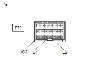
F70-21 (IG2) - Body ground |
Ignition switch ON |
8 to 16 V |
(e) Turn the ignition switch off.
(f) Measure the resistance according to the value(s) in the table below.
Standard Resistance:
|
Tester Connection |
Condition |
Specified Condition |
|---|---|---|
|
F70-25 (E1) - Body ground |
Always |
Below 1 Ω |
|
F70-26 (E2) - Body ground |
Always |
Below 1 Ω |
| NG | |
REPLACE WIRE HARNESS |
|
|
5. |
CHECK SRS WARNING LIGHT |
(a) Turn the ignition switch ON and check the SRS warning light condition.
OK:
After the primary check period, the SRS warning light turns off for approximately 10 seconds and then turns back on.
HINT:
The primary check period is approximately 6 seconds after the ignition switch is turned ON.
| OK | |
REPLACE AIRBAG SENSOR ASSEMBLY |
| NG | |
REPLACE COMBINATION METER ASSEMBLY |
|
6. |
CHECK CAN COMMUNICATION SYSTEM |
(a) Using the Techstream, check if the CAN communication system is functioning normally.
OK:
CAN communication system is functioning normally.
HINT:
Refer to CAN Bus Check in CAN Communication System.
Click here
| NG | |
GO TO CAN COMMUNICATION SYSTEM |
|
|
7. |
CHECK BATTERY VOLTAGE |
(a) Measure the voltage of the battery.
Standard Voltage:
11 to 14 V
| NG | |
INSPECT CHARGING SYSTEM AND BATTERY |
|
|
8. |
CHECK CONNECTOR |
(a) Turn the ignition switch off.
(b) Disconnect the cable from the negative (-) battery terminal.
CAUTION:
Wait at least 90 seconds after disconnecting the cable from the negative (-) battery terminal to disable the SRS system.
(c) Check that the connector is properly connected to the airbag sensor assembly.
OK:
The connector is properly connected.
HINT:
If the connector is not properly connected, reconnect the connector and proceed to the next inspection.
(d) Disconnect the connector from the airbag sensor assembly.
(e) Check that the terminals of the connector are not deformed or damaged.
OK:
The terminals are not deformed or damaged.
| NG | |
REPLACE WIRE HARNESS |
|
|
9. |
CHECK WIRE HARNESS (AIRBAG SENSOR ASSEMBLY - BODY GROUND) |
|
(a) Connect the cable to the negative (-) battery terminal. |
|

(b) Turn the ignition switch ON.
(c) Operate all components of the electrical systems (defogger, wipers, headlights, heater blower, etc.).
(d) Measure the voltage according to the value(s) in the table below.
Standard Voltage:
|
Tester Connection |
Switch Condition |
Specified Condition |
|---|---|---|
|
F70-21 (IG2) - Body ground |
Ignition switch ON |
8 to 16 V |
(e) Turn the ignition switch off.
(f) Measure the resistance according to the value(s) in the table below.
Standard Resistance:
|
Tester Connection |
Condition |
Specified Condition |
|---|---|---|
|
F70-25 (E1) - Body ground |
Always |
Below 1 Ω |
|
F70-26 (E2) - Body ground |
Always |
Below 1 Ω |
| NG | |
REPLACE WIRE HARNESS |
|
|
10. |
CHECK CONNECTOR |
(a) Disconnect the cable from the negative (-) battery terminal.
CAUTION:
Wait at least 90 seconds after disconnecting the cable from the negative (-) battery terminal to disable the SRS system.
(b) Check that the connector is properly connected to the combination meter assembly.
OK:
The connector is properly connected.
HINT:
If the connector is not properly connected, reconnect the connector and proceed to the next inspection.
(c) Disconnect the connector from the combination meter assembly.
(d) Check that the terminals of the connector are not deformed or damaged.
OK:
The terminals are not deformed or damaged.
| NG | |
REPAIR OR REPLACE CONNECTOR |
|
|
11. |
CHECK WIRE HARNESS (COMBINATION METER ASSEMBLY - BODY GROUND) |
|
(a) Connect the cable to the negative (-) battery terminal. |
|
(b) Turn the ignition switch ON.
(c) Measure the voltage according to the value(s) in the table below.
Standard Voltage:
|
Tester Connection |
Switch Condition |
Specified Condition |
|---|---|---|
|
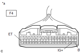
F4-39 (IG+) - Body ground |
Ignition switch ON |
11 to 14 V |
|
F4-40 (B) - Body ground |
Ignition switch off |
11 to 14 V |
(d) Turn the ignition switch off.
(e) Measure the resistance according to the value(s) in the table below.
Standard Resistance:
|
Tester Connection |
Condition |
Specified Condition |
|---|---|---|
|
F4-21 (ET) - Body ground |
Always |
Below 1 Ω |
| NG | |
REPAIR OR REPLACE WIRE HARNESS |
|
|
12. |
CHECK SRS WARNING LIGHT |
(a) Disconnect the cable from the negative (-) battery terminal.
CAUTION:
Wait at least 90 seconds after disconnecting the cable from the negative (-) battery terminal to disable the SRS system.
(b) Connect the connector to the combination meter assembly.
(c) Connect the cable to the negative (-) battery terminal.
(d) Turn the ignition switch ON and check the SRS warning light condition.
OK:
After the primary check period, the SRS warning light turns off for approximately 10 seconds and then turns back on.
HINT:
The primary check period is approximately 6 seconds after the ignition switch is turned ON.
| OK | |
REPLACE AIRBAG SENSOR ASSEMBLY |
| NG | |
REPLACE COMBINATION METER ASSEMBLY |
 Short in Curtain Shield Squib LH Circuit (B1835/58-B1838/58)
DESCRIPTION
The curtain shield squib LH circuit consists of the airbag sensor assembly and
curtain shield airbag assembly LH.
The airbag sensor assembly uses this circuit to deploy the airbag when ...
 SRS Warning Light does not Come ON
DESCRIPTION
The SRS warning light is located in the combination meter assembly.
When the SRS is normal, the SRS warning light comes on for approximately 6 seconds
after the ignition switch is turn ...
Other materials:
Toyota CH-R Service Manual > Front Disc Brake Pad: Installation
INSTALLATION
CAUTION / NOTICE / HINT
NOTICE:
Immediately after installing the brake pads, the braking performance
may be reduced. Always perform a road test in a safe place while paying
attention to the surroundings.
Immediately after installing the front disc brake pads, the ...
Toyota CH-R Service Manual > Compressor(for Valeo Made): Components
COMPONENTS
ILLUSTRATION
*1
COMPRESSOR WITH PULLEY ASSEMBLY
*2
DISCHARGE HOSE SUB-ASSEMBLY
*3
NO. 1 ENGINE UNDER COVER
*4
SUCTION HOSE SUB-ASSEMBLY
*5
O-RING
-
...
Toyota C-HR (AX20) 2023-2026 Owner's Manual
Toyota CH-R Owners Manual
- For safety and security
- Instrument cluster
- Operation of each component
- Driving
- Interior features
- Maintenance and care
- When trouble arises
- Vehicle specifications
- For owners
Toyota CH-R Service Manual
- Introduction
- Maintenance
- Audio / Video
- Cellular Communication
- Navigation / Multi Info Display
- Park Assist / Monitoring
- Brake (front)
- Brake (rear)
- Brake Control / Dynamic Control Systems
- Brake System (other)
- Parking Brake
- Axle And Differential
- Drive Shaft / Propeller Shaft
- K114 Cvt
- 3zr-fae Battery / Charging
- Networking
- Power Distribution
- Power Assist Systems
- Steering Column
- Steering Gear / Linkage
- Alignment / Handling Diagnosis
- Front Suspension
- Rear Suspension
- Tire / Wheel
- Tire Pressure Monitoring
- Door / Hatch
- Exterior Panels / Trim
- Horn
- Lighting (ext)
- Mirror (ext)
- Window / Glass
- Wiper / Washer
- Door Lock
- Heating / Air Conditioning
- Interior Panels / Trim
- Lighting (int)
- Meter / Gauge / Display
- Mirror (int)
- Power Outlets (int)
- Pre-collision
- Seat
- Seat Belt
- Supplemental Restraint Systems
- Theft Deterrent / Keyless Entry

0.0084