Toyota CH-R Service Manual: Engine Immobiliser System Malfunction (B2799)
DESCRIPTION
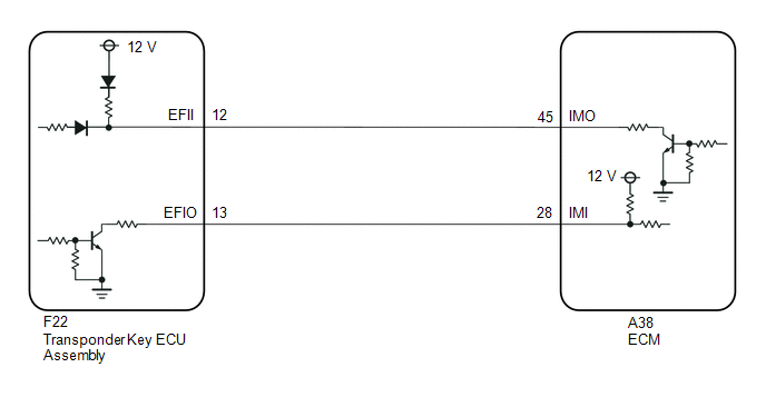
The ECM stores this DTC when the communication line between the ECM and transponder key ECU assembly is malfunctioning or the communication ID of the ECM and transponder key ECU assembly do not match.
|
DTC No. |
Detection Item |
DTC Detection Condition |
Trouble Area |
Note |
|---|---|---|---|---|
|
B2799 |
Engine Immobiliser System Malfunction |
Either condition is met (1 trip detection logic*2):
|
|
DTC Output Confirmation Operation:
|
|
Vehicle Condition |
|||
|---|---|---|---|
|
Pattern 1 |
Pattern 2 |
||
|
Diagnosis Condition |
Engine start operation. |
○ |
○ |
|
Malfunction Status |
A malfunction occurs in the communication or communication lines between the ECM and transponder key ECU assembly. |
○ |
- |
|
A communication code cannot be verified during communication between the ECM and transponder key ECU assembly. |
- |
○ |
|
|
Detection Time |
- |
- |
|
|
Number of Trips |
1 trip |
1 trip |
|
HINT:
DTC will be output when conditions for either of the patterns in the table above are met.
Vehicle Condition and Fail-safe Operation when Malfunction Detected|
Vehicle Condition when Malfunction Detected |
Fail-safe Operation when Malfunction Detected |
|---|---|
|
Engine cannot be started |
- |
|
DTC No. |
Data List and Active Test |
|---|---|
|
B2799 |
- |
WIRING DIAGRAM
CAUTION / NOTICE / HINT
NOTICE:
- If the transponder key ECU assembly or ECM is replaced, refer to Registration.
Click here
.gif)
- After repair, confirm that no DTCs are output by performing "DTC Output Confirmation Operation".
HINT:
If transponder key ECU assembly DTCs are output simultaneously, troubleshoot the transponder key ECU assembly DTCs first.
PROCEDURE
|
1. |
CLEAR DTC |
(a) Clear the DTCs.
Powertrain > Engine and ECT > Clear DTCs
|
.gif)
|
2. |
CHECK FOR DTC |
(a) Start the engine.
(b) Check for DTCs.
Powertrain > Engine and ECT > Trouble CodesHINT:
Before checking for DTCs, perform the "DTC Output Confirmation Operation" procedure.
OK:
B2799 is not output.
|
Result |
Proceed to |
|---|---|
|
OK |
A |
|
NG (DTC B2799 is output) |
B |
|
NG (Other DTCs are output) |
C |
| A | .gif) |
USE SIMULATION METHOD TO CHECK |
| C | |
GO TO DIAGNOSTIC TROUBLE CODE CHART |
|
|
3. |
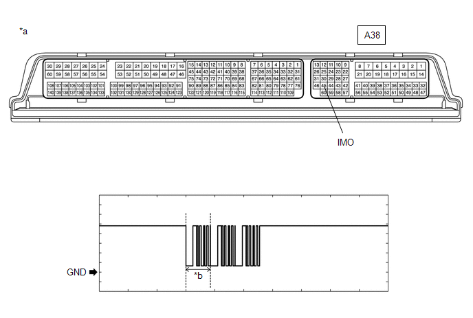
INSPECT ECM (TERMINAL IMO) |
(a) Using an oscilloscope, check the waveform
|
*a |
Component with harness connected (ECM) |
*b |
Waveform |
|
Item |
Content |
|---|---|
|
Tester Connection |
A38-45 (IMO) - Body ground |
|
Tool Setting |
2 V/DIV., 500 ms./DIV. |
|
Condition |
Within 3 seconds of starter operation and initial combustion, or within 3 seconds of ignition switch first being turned to ON after cable disconnected and reconnected to negative (-) battery terminal |
|
Result |
Proceed to |
|---|---|
|
OK |
A |
|
NG (Terminal IMO stuck low (2.4 V or less)) |
B |
|
NG (Terminal IMO stuck high (12 V) or abnormal waveform) |
C |
| B | |
GO TO STEP 10 |
| C | |
GO TO STEP 7 |
|
|
4. |
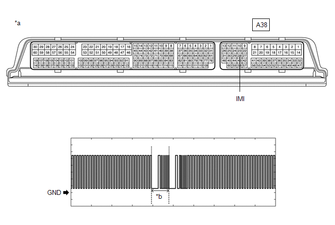
INSPECT ECM (TERMINAL IMI) |
(a) Using an oscilloscope, check the waveform
|
*a |
Component with harness connected (ECM) |
*b |
Waveform |
|
Item |
Content |
|---|---|
|
Tester Connection |
A38-28 (IMI) - Body ground |
|
Tool Setting |
2 V/DIV., 500 ms./DIV. |
|
Condition |
Ignition switch ON |
OK:
Waveform is similar to that shown in the illustration.
|
Result |
Proceed to |
|---|---|
|
OK |
A |
|
NG |
B |
| B | |
GO TO STEP 12 |
|
|
5. |
REGISTER ECU COMMUNICATION ID |
(a) Reregister the ECU communication ID.
HINT:
Refer to Registration.
Click here
|
|
6. |
CHECK WHETHER ENGINE STARTS |
(a) Using a registered key, turn the ignition switch to ON.
(b) Check that the engine starts 5 seconds after the ignition switch was turned to ON.
OK:
Engine starts normally.
| OK | |
END (COMMUNICATION ID REGISTRATION WAS DEFECTIVE) |
|
|
7. |
REPLACE ECM |
(a) Temporarily replace the ECM with a new one.
Click here
|
|
8. |
REGISTER ECU COMMUNICATION ID |
(a) Reregister the ECU communication ID.
HINT:
Refer to Registration.
|
|
9. |
CHECK WHETHER ENGINE STARTS |
(a) Using a registered key, turn the ignition switch to ON.
(b) Check that the engine starts 5 seconds after the ignition switch was turned to ON.
OK:
Engine starts normally.
| OK | |
END (ECM WAS DEFECTIVE) |
| NG | |
REPLACE TRANSPONDER KEY ECU ASSEMBLY |
|
10. |
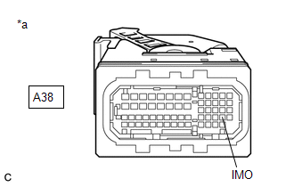
INSPECT ECM (IMO TERMINAL VOLTAGE) |
(a) Disconnect the A38 ECM connector
(b) Turn the ignition switch to ON
|
(c) Measure the voltage according to the value(s) in the table below Standard Voltage:
|
|
|
Result |
Proceed to |
|---|---|
|
Terminal IMO stuck low (2.4 V or less) |
A |
|
Terminal IMO stuck high (12 V) or Abnormal waveform |
B |
| B | |
GO TO STEP 7 |
|
|
11. |
CHECK HARNESS AND CONNECTOR (TRANSPONDER KEY ECU - ECM AND BODY GROUND) |
(a) Disconnect the F22 transponder key ECU assembly connector
(b) Disconnect the A38 ECM connector
(c) Measure the resistance according to the value(s) in the table below
Standard Resistance:
|
Tester Connection |
Condition |
Specified Condition |
|---|---|---|
|
F22-12 (EFII) - A38-45 (IMO) |
Always |
Below 1 Ω |
|
A38-45 (IMO) - Body ground |
Always |
10 kΩ or higher |
|
F22-12 (EFII) - Body ground |
Always |
10 kΩ or higher |
|
F22-13 (EFIO) - A38-28 (IMI) |
Always |
Below 1 Ω |
|
A38-28 (IMI) - Body ground |
Always |
10 kΩ or higher |
|
F22-13 (EFIO) - Body ground |
Always |
10 kΩ or higher |
| NG | |
REPAIR OR REPLACE HARNESS OR CONNECTOR |
|
|
12. |
REPLACE TRANSPONDER KEY ECU ASSEMBLY |
(a) Replace the transponder key ECU assembly with a new one.
Click here
HINT:
Refer to Registration.
Click here
NOTICE:
Key ID code registration is necessary when replacing the transponder key ECU assembly.
Click here
|
|
13. |
CHECK WHETHER ENGINE STARTS |
(a) Using a registered key, turn the ignition switch to ON.
(b) Check that the engine starts 5 seconds after the ignition switch was turned to ON.
OK:
Engine starts normally.
| OK | |
END (TRANSPONDER KEY ECU ASSEMBLY WAS DEFECTIVE) |
| NG | |
REPLACE ECM |
 Theft Deterrent System Communication Line High Fixation (B279A)
DESCRIPTION
If the communication line (EFIO-IMI) to the transponder key ECU assembly is stuck
high (e.g. shorted to +B), the ECM stores this DTC.
DTC No.
Detection Item
...
 No Communication in Immobiliser System (B2796)
DESCRIPTION
This DTC is stored when a key is inserted into the ignition key cylinder but
no communication occurs between the key and transponder key ECU assembly.
DTC No.
Det ...
Other materials:
Toyota CH-R Service Manual > Audio And Visual System(for Radio And Display Type): Certification ECU Vehicle Information Reading/Writing Process Malfunction (B15F7)
DESCRIPTION
This DTC is stored when items controlled by the certification ECU (smart key
ECU assembly) cannot be customized via the audio and visual system vehicle customization
screen.
HINT:
The certification ECU (smart key ECU assembly) controls the smart key system
related items that are ...
Toyota CH-R Service Manual > Electric Parking Brake System: EPB Switch Malfunction (C13B4)
DESCRIPTION
When the electric parking brake switch is pulled, a lock request signal is sent
from the skid control ECU (brake actuator assembly) to the parking brake actuator
assembly. When the electric parking brake switch is pushed, a release request signal
is sent from the skid control ECU ...
Toyota C-HR (AX20) 2023-2026 Owner's Manual
Toyota CH-R Owners Manual
- For safety and security
- Instrument cluster
- Operation of each component
- Driving
- Interior features
- Maintenance and care
- When trouble arises
- Vehicle specifications
- For owners
Toyota CH-R Service Manual
- Introduction
- Maintenance
- Audio / Video
- Cellular Communication
- Navigation / Multi Info Display
- Park Assist / Monitoring
- Brake (front)
- Brake (rear)
- Brake Control / Dynamic Control Systems
- Brake System (other)
- Parking Brake
- Axle And Differential
- Drive Shaft / Propeller Shaft
- K114 Cvt
- 3zr-fae Battery / Charging
- Networking
- Power Distribution
- Power Assist Systems
- Steering Column
- Steering Gear / Linkage
- Alignment / Handling Diagnosis
- Front Suspension
- Rear Suspension
- Tire / Wheel
- Tire Pressure Monitoring
- Door / Hatch
- Exterior Panels / Trim
- Horn
- Lighting (ext)
- Mirror (ext)
- Window / Glass
- Wiper / Washer
- Door Lock
- Heating / Air Conditioning
- Interior Panels / Trim
- Lighting (int)
- Meter / Gauge / Display
- Mirror (int)
- Power Outlets (int)
- Pre-collision
- Seat
- Seat Belt
- Supplemental Restraint Systems
- Theft Deterrent / Keyless Entry

0.0073