Toyota CH-R Service Manual: Theft Deterrent System Communication Line High Fixation (B279A)
DESCRIPTION
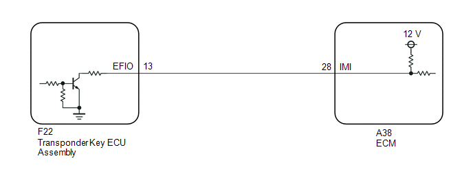
If the communication line (EFIO-IMI) to the transponder key ECU assembly is stuck high (e.g. shorted to +B), the ECM stores this DTC.
|
DTC No. |
Detection Item |
DTC Detection Condition |
Trouble Area |
Note |
|---|---|---|---|---|
|
B279A |
Theft Deterrent System Communication Line High Fixation |
Communication line (EFIO-IMI) between the ECM and transponder key ECU assembly is stuck high. |
|
|
|
Vehicle Condition when Malfunction Detected |
Fail-safe Operation when Malfunction Detected |
|---|---|
|
Engine cannot be started (initial ignition occurs and engine cranks, then ignition stops) |
Engine cannot be started |
|
DTC No. |
Data List and Active Test |
|---|---|
|
B279A |
- |
WIRING DIAGRAM
CAUTION / NOTICE / HINT
NOTICE:
- If the transponder key ECU assembly or ECM is replaced, refer to Registration.
Click here
.gif)
- After repair, confirm that no DTCs are output by performing "DTC Output Confirmation Operation".
PROCEDURE
|
1. |
CLEAR DTC |
(a) Clear the DTCs.
Powertrain > Engine and ECT > Clear DTCs
|
.gif)
|
2. |
CHECK FOR DTC |
(a) Check for DTCs.
Powertrain > Engine and ECT > Trouble CodesHINT:
Before checking for DTCs, perform the "DTC Output Confirmation Operation" procedure.
OK:
DTC B279A is not output.
|
Result |
Proceed to |
|---|---|
|
B279A is not output |
A |
|
B279A is output |
B |
| A | .gif) |
USE SIMULATION METHOD TO CHECK |
|
|
3. |
CHECK CONNECTION OF CONNECTOR |
(a) Check that the connectors are properly connected to the ECM and transponder key ECU assembly.
OK:
Connectors are properly connected.
| NG | |
CONNECT CONNECTORS PROPERLY |
|
|
4. |
CHECK HARNESS AND CONNECTOR (TRANSPONDER KEY ECU ASSEMBLY - ECM AND BODY GROUND) |
(a) Disconnect the F22 transponder key ECU assembly connector
(b) Disconnect the A38 ECM connector
(c) Measure the resistance according to the value(s) in the table below
Standard Resistance:
|
Tester Connection |
Condition |
Specified Condition |
|---|---|---|
|
F22-13 (EFIO) - A38-28 (IMI) |
Always |
Below 1 Ω |
|
F22-13 (EFIO) - Body ground |
Always |
10 kΩ or higher |
|
A38-28 (IMI) - Body ground |
Always |
10 kΩ or higher |
| NG | |
REPAIR OR REPLACE HARNESS OR CONNECTOR |
|
|
5. |
REPLACE TRANSPONDER KEY ECU ASSEMBLY |
(a) Replace the transponder key ECU assembly with a new one.
Click here
|
|
6. |
CLEAR DTC |
(a) Clear the DTCs.
Powertrain > Engine and ECT > Clear DTCs
|
|
7. |
CHECK FOR DTC |
(a) Check for DTCs.
Powertrain > Engine and ECT > Trouble CodesHINT:
Before checking for DTCs, perform the "DTC Output Confirmation Operation" procedure.
OK:
DTC B279A is not output.
|
Result |
Proceed to |
|---|---|
|
B279A is not output |
A |
|
B279A is output |
B |
| A | |
END (TRANSPONDER KEY ECU ASSEMBLY WAS DEFECTIVE) |
| B | |
REPLACE ECM |
 Diagnostic Trouble Code Chart
DIAGNOSTIC TROUBLE CODE CHART
Immobiliser System
DTC No.
Detection Item
Link
B2780
Push Switch / Key Unlock Warning Switch Malfunction
...
 Engine Immobiliser System Malfunction (B2799)
DESCRIPTION
The ECM stores this DTC when the communication line between the ECM and transponder
key ECU assembly is malfunctioning or the communication ID of the ECM and transponder
key ECU assem ...
Other materials:
Toyota CH-R Service Manual > Cellular Communication: Telephone And Gps Antenna(for Roof Side)
Components
COMPONENTS
ILLUSTRATION
*1
TELEPHONE AND GPS ANTENNA ASSEMBLY
*2
ANTENNA OUTER COVER
*3
HOLDER
*4
SEAL
N*m (kgf*cm, ft.*lbf): Specified torque
●
...
Toyota CH-R Service Manual > Lighting System: Daytime Running Light Relay Circuit
DESCRIPTION
The main body ECU (multiplex network body ECU) controls the daytime running lights.
WIRING DIAGRAM
CAUTION / NOTICE / HINT
NOTICE:
Inspect the fuses for circuits related to this system before performing
the following procedure.
Before replacing the main body ECU (m ...
Toyota C-HR (AX20) 2023-2026 Owner's Manual
Toyota CH-R Owners Manual
- For safety and security
- Instrument cluster
- Operation of each component
- Driving
- Interior features
- Maintenance and care
- When trouble arises
- Vehicle specifications
- For owners
Toyota CH-R Service Manual
- Introduction
- Maintenance
- Audio / Video
- Cellular Communication
- Navigation / Multi Info Display
- Park Assist / Monitoring
- Brake (front)
- Brake (rear)
- Brake Control / Dynamic Control Systems
- Brake System (other)
- Parking Brake
- Axle And Differential
- Drive Shaft / Propeller Shaft
- K114 Cvt
- 3zr-fae Battery / Charging
- Networking
- Power Distribution
- Power Assist Systems
- Steering Column
- Steering Gear / Linkage
- Alignment / Handling Diagnosis
- Front Suspension
- Rear Suspension
- Tire / Wheel
- Tire Pressure Monitoring
- Door / Hatch
- Exterior Panels / Trim
- Horn
- Lighting (ext)
- Mirror (ext)
- Window / Glass
- Wiper / Washer
- Door Lock
- Heating / Air Conditioning
- Interior Panels / Trim
- Lighting (int)
- Meter / Gauge / Display
- Mirror (int)
- Power Outlets (int)
- Pre-collision
- Seat
- Seat Belt
- Supplemental Restraint Systems
- Theft Deterrent / Keyless Entry

0.0083