Toyota CH-R Service Manual: No Communication in Immobiliser System (B2796)
DESCRIPTION
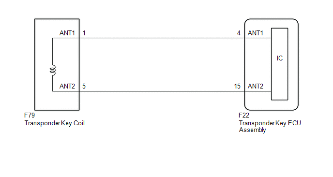
This DTC is stored when a key is inserted into the ignition key cylinder but no communication occurs between the key and transponder key ECU assembly.
|
DTC No. |
Detection Item |
DTC Detection Condition |
Trouble Area |
Note |
|---|---|---|---|---|
|
B2796 |
No Communication in Immobiliser System |
The key ID code cannot be transmitted to the transponder key ECU assembly (1 trip detection logic*). |
|
|
- *: Only output while a malfunction is present.
|
Vehicle Condition when Malfunction Detected |
Fail-safe Operation when Malfunction Detected |
|---|---|
|
Engine cannot be started |
- |
|
DTC No. |
Data List and Active Test |
|---|---|
|
B2796 |
- |
WIRING DIAGRAM
CAUTION / NOTICE / HINT
NOTICE:
- If the transponder key ECU assembly or key is replaced, refer to Registration.
Click here
.gif)
- After repair, confirm that no DTCs are output by performing "DTC Output Confirmation Operation".
PROCEDURE
|
1. |
CLEAR DTC |
(a) Clear the DTCs.
Body Electrical > Immobiliser > Clear DTCs
|
.gif)
|
2. |
CHECK FOR DTC |
(a) Insert and remove each registered key one at a time, and check for DTCs each time.
Body Electrical > Immobiliser > Trouble CodesHINT:
Before checking for DTCs, perform the "DTC Output Confirmation Operation" procedure.
OK:
B2796 is not output.
|
Result |
Proceed to |
|---|---|
|
B2796 is not output |
A |
|
DTC B2796 is output for all of the keys |
B |
|
DTC B2796 is output for any of the keys |
C |
| A | .gif) |
USE SIMULATION METHOD TO CHECK |
| C | |
GO TO STEP 6 |
|
|
3. |
REPLACE TRANSPONDER KEY ECU ASSEMBLY |
(a) Replace the transponder key ECU assembly with a new one.
Click here
HINT:
Refer to Registration.
Click here
NOTICE:
Key ID code registration is necessary when replacing the transponder key ECU assembly.
Click here
|
|
4. |
CLEAR DTC |
(a) Clear the DTCs.
Body Electrical > Immobiliser > Clear DTCs
|
|
5. |
CHECK FOR DTC |
(a) Check for DTCs.
Body Electrical > Immobiliser > Trouble CodesHINT:
Before checking for DTCs, perform the "DTC Output Confirmation Operation" procedure.
OK:
DTC B2796 is not output.
|
Result |
Proceed to |
|---|---|
|
B2796 is not output |
A |
|
B2796 is output |
B |
| A | |
END (TRANSPONDER KEY ECU ASSEMBLY WAS DEFECTIVE) |
| B | |
REPLACE KEY THAT DTC IS OUTPUT |
|
6. |
REPLACE KEY |
(a) Replace the key for which the DTC was stored.
NOTICE:
Key ID code registration is necessary when replacing the key.
Click here
|
|
7. |
CLEAR DTC |
(a) Clear the DTCs.
Body Electrical > Immobiliser > Clear DTCs
|
|
8. |
CHECK FOR DTC |
(a) Check for DTCs.
Body Electrical > Immobiliser > Trouble CodesHINT:
Before checking for DTCs, perform the "DTC Output Confirmation Operation" procedure.
OK:
DTC B2796 is not output.
|
Result |
Proceed to |
|---|---|
|
B2796 is not output |
A |
|
B2796 is output |
B |
| A | |
END (KEY WAS DEFECTIVE) |
| B | |
REPLACE TRANSPONDER KEY ECU ASSEMBLY |
 Engine Immobiliser System Malfunction (B2799)
DESCRIPTION
The ECM stores this DTC when the communication line between the ECM and transponder
key ECU assembly is malfunctioning or the communication ID of the ECM and transponder
key ECU assem ...
 Transponder Chip Malfunction (B2793,B2794,B2797,B2798)
DESCRIPTION
DTC B2793 is stored when a malfunction is found in the key during key
ID code registration or a key ID code is not registered normally. Replace
the key if key ID code regis ...
Other materials:
Toyota CH-R Service Manual > Power Window Control System: Operation Check
OPERATION CHECK
CHECK WINDOW LOCK FUNCTION
HINT:
Before performing the window lock switch operation check, make sure that the
window lock switch is off (the switch is not pushed in).
(a) Turn the window lock switch of the multiplex network master switch assembly
on (pushed in) and check th ...
Toyota CH-R Service Manual > Seat Belt Warning System(w/ Occupant Classification System): System Diagram
SYSTEM DIAGRAM
FRONT SEAT BELT WARNING
Communication Table
Sender
Receiver
Signal
Communication Method
Airbag sensor assembly
Combination meter assembly
Front seat inner belt assembly LH buckle switch ...
Toyota C-HR (AX20) 2023-2026 Owner's Manual
Toyota CH-R Owners Manual
- For safety and security
- Instrument cluster
- Operation of each component
- Driving
- Interior features
- Maintenance and care
- When trouble arises
- Vehicle specifications
- For owners
Toyota CH-R Service Manual
- Introduction
- Maintenance
- Audio / Video
- Cellular Communication
- Navigation / Multi Info Display
- Park Assist / Monitoring
- Brake (front)
- Brake (rear)
- Brake Control / Dynamic Control Systems
- Brake System (other)
- Parking Brake
- Axle And Differential
- Drive Shaft / Propeller Shaft
- K114 Cvt
- 3zr-fae Battery / Charging
- Networking
- Power Distribution
- Power Assist Systems
- Steering Column
- Steering Gear / Linkage
- Alignment / Handling Diagnosis
- Front Suspension
- Rear Suspension
- Tire / Wheel
- Tire Pressure Monitoring
- Door / Hatch
- Exterior Panels / Trim
- Horn
- Lighting (ext)
- Mirror (ext)
- Window / Glass
- Wiper / Washer
- Door Lock
- Heating / Air Conditioning
- Interior Panels / Trim
- Lighting (int)
- Meter / Gauge / Display
- Mirror (int)
- Power Outlets (int)
- Pre-collision
- Seat
- Seat Belt
- Supplemental Restraint Systems
- Theft Deterrent / Keyless Entry

0.008