Toyota CH-R Service Manual: Terminals Of Ecu
TERMINALS OF ECU
CHECK TRANSPONDER KEY ECU ASSEMBLY
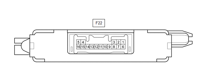
(a) Disconnect the F22 transponder key ECU assembly connector.
(b) Measure the resistance and voltage according to the value(s) in the table below.
HINT:
Measure the values on the wire harness side with the connector disconnected.
|
Tester Connection |
Input/Output |
Wiring Color |
Terminal Description |
Condition |
Specified Condition |
Related Data List Item |
|---|---|---|---|---|---|---|
|
F22-1 (+B) - F22-5 (GND) |
Input |
W - W-B |
Battery |
Always |
11 to 14 V |
+B |
|
F22-2 (IG) - F22-5 (GND) |
Input |
B - W-B |
Ignition switch signal |
Ignition switch off |
Below 1 V |
IG SW |
|
Ignition switch ON |
11 to 14 V |
|||||
|
F22-3 (KSW) - F22-5 (GND) |
Input |
V - W-B |
Unlock warning switch signal |
No key in ignition key cylinder |
10 kΩ or higher |
Key SW/B2780 |
|
Key in ignition key cylinder |
Below 1 Ω |
|||||
|
F22-5 (GND) - Body ground |
- |
W-B - Body ground |
Ground |
Always |
Below 1 Ω |
- |
If the result is not as specified, there may be a malfunction on the wire harness side.
(c) Reconnect the F22 transponder key ECU assembly connector.
(d) Measure the voltage and check for pulses according to the value(s) in the table below.
|
Tester Connection |
Input/Output |
Wiring Color |
Terminal Description |
Condition |
Specified Condition |
Related Data List Item |
|---|---|---|---|---|---|---|
|
F22-8 (IND) - F22-5 (GND) |
Output |
P - W-B |
Security indicator signal |
No key in ignition key cylinder, or 20 sec. elapsed after turning ignition switch to ACC or off (immobiliser system set) |
Pulse generation |
Immobiliser |
|
Key in ignition key cylinder (immobiliser system unset) |
Below 1 V |
|||||
|
F22-9 (D) - F22-5 (GND) |
Input/Output |
SB - W-B |
DLC3 communication |
Without communication |
Below 1 V |
- |
|
During communication |
Pulse generation |
|||||
|
F22-4 (ANT1) - F22-5 (GND) |
Input/Output |
V - W-B |
Transponder key amplifier power source |
No key in ignition key cylinder |
4 to 6 V |
- |
|
Within 3 seconds of inserting key into ignition key cylinder |
Pulse generation (See waveform 1) |
|||||
|
F22-15 (ANT2) - F22-5 (GND) |
Input/Output |
W - W-B |
Transponder key amplifier communication signal |
No key in ignition key cylinder |
4 to 6 V |
- |
|
Within 3 seconds of inserting key into ignition key cylinder |
Pulse generation (See waveform 2) |
|||||
|
F22-12 (EFII) - F22-5 (GND) |
Output |
G - W-B |
ECM input signal |
Within 3 seconds of starter operation and initial combustion, or within 3 seconds of ignition switch first being turned to ON after cable disconnected and reconnected to negative (-) battery terminal |
Pulse generation (See waveform 3) |
- |
|
F22-13 (EFIO) - F22-5 (GND) |
Input |
R - W-B |
ECM output signal |
Ignition switch off |
Below 1 V |
- |
|
Ignition switch ON |
Pulse generation (See waveform 4) |
If the result is not as specified, the transponder key ECU assembly may be malfunctioning.
(e) Using an oscilloscope, check the waveform.
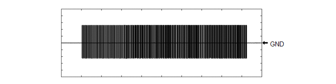
(1) Waveform 1 (Reference)
|
Tester Connection |
F22-4 (ANT1) - F22-5 (GND) |
|
Tool Setting |
20 V/DIV., 2 s./DIV. |
|
Condition |
Within 3 seconds of inserting key into ignition key cylinder |
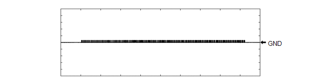
(2) Waveform 2 (Reference)
|
Tester Connection |
F22-15 (ANT2) - F22-5 (GND) |
|
Tool Setting |
20 V/DIV., 2 s./DIV. |
|
Condition |
Within 3 seconds of inserting key into ignition key cylinder |
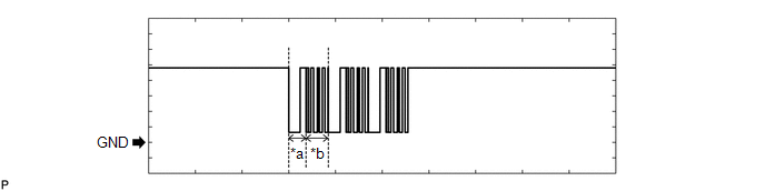
(3) Waveform 3 (Reference)
|
*a |
Approximately 160 ms |
*b |
Approximately 270 ms |
|
Tester Connection |
F22-12 (EFII) - F22-5 (GND) |
|
Tool Setting |
2 V/DIV., 500 ms./DIV. |
|
Condition |
Within 3 seconds of starter operation and initial combustion, or within 3 seconds of ignition switch first being turned to ON after cable disconnected and reconnected to negative (-) battery terminal |
(4) Waveform 4 (Reference)
|
*a |
Approximately 160 ms |
*b |
Approximately 270 ms |
|
Tester Connection |
F22-13 (EFIO) - F22-5 (GND) |
|
Tool Setting |
2 V/DIV., 500 ms./DIV. |
|
Condition |
Ignition switch ON |
CHECK ECM
(a) Measure the voltage and resistance, and check for pulses according to the value(s) in the table below.
|
Terminal No. (Symbol) |
Input/Output |
Wiring Color |
Terminal Description |
Condition |
Specified Condition |
Related Data List Item/DTC |
|---|---|---|---|---|---|---|
|
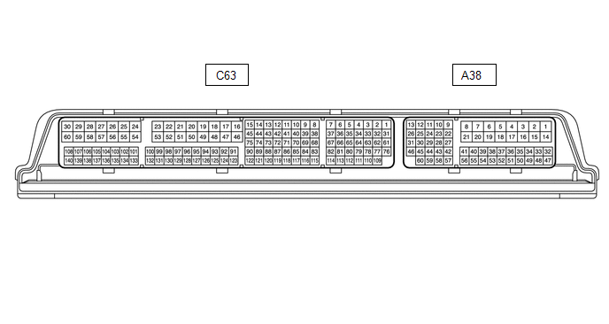
C63-59 (E1) - Body ground |
- |
W-B - Body ground |
Ground |
Always |
Below 1 Ω |
- |
|
A38-45 (IMO) - C63-59 (E1) |
Output |
GR - W-B |
ID code box (immobiliser code ECU) communication output |
Ignition switch off |
11 to 14 V |
- |
|
A38-45 (IMO) - C63-59 (E1) |
Output |
GR - W-B |
ID code box (immobiliser code ECU) communication output |
Within 3 seconds of engine start or within 3 seconds of ignition switch turned ON after cable disconnected and reconnected to battery |
Pulse generation (See waveform 1) |
- |
|
A38-28 (IMI) - C63-59 (E1) |
Input |
BE - W-B |
ID code box (immobiliser code ECU) communication input |
Ignition switch off |
11 to 14 V |
- |
|
A38-28 (IMI) - C63-59 (E1) |
Input |
BE - W-B |
ID code box (immobiliser code ECU) communication input |
Ignition switch turned ON using registered electrical key transmitter sub-assembly |
Pulse generation (See waveform 2) |
- |
(b) Using an oscilloscope, check the waveform.
NOTICE:
The waveform shown in the illustration is an example for reference only. Noise, chattering, etc. are not shown.
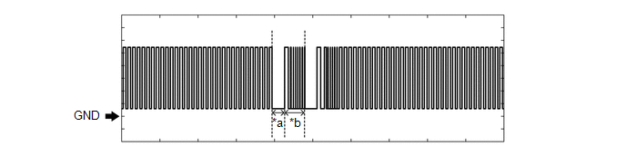
(1) Waveform 1 (Reference)
.png)
|
*a |
Approximately 160 ms. |
*b |
Approximately 270 ms. |
|
Item |
Content |
|---|---|
|
Tester Connection |
A38-45 (IMO) - C63-59 (E1) |
|
Tool Setting |
2 V/DIV., 500 ms./DIV. |
|
Condition |
Within 3 seconds of engine start or within 3 seconds of ignition switch turned ON after cable disconnected and reconnected to battery |
(2) Waveform 2 (Reference)
.png)
|
*a |
Approximately 160 ms. |
*b |
Approximately 270 ms. |
|
Item |
Content |
|---|---|
|
Tester Connection |
A38-28 (IMI) - C63-59 (E1) |
|
Tool Setting |
2 V/DIV., 500 ms./DIV. |
|
Condition |
Ignition switch turned ON using registered electrical key transmitter sub-assembly |
 Registration
REGISTRATION
PROCEDURE
1. DESCRIPTION OF CODE REGISTRATION
(a) The door control transmitter assembly has 2 codes: the key code (immobiliser
code) and the wireless code. Both of these codes need t ...
 Diagnosis System
DIAGNOSIS SYSTEM
DESCRIPTION
(a) The transponder key ECU assembly controls the immobiliser system. Immobiliser
system data and Diagnostic Trouble Codes (DTCs) can be read through the vehicle
Dat ...
Other materials:
Toyota CH-R Service Manual > Vehicle Stability Control System: Acceleration Sensor Stuck Malfunction (C1243,C1245)
DESCRIPTION
The skid control ECU (brake actuator assembly) receives signals from the yaw
rate and acceleration sensor (airbag sensor assembly) via CAN communication.
The airbag sensor assembly has a built-in yaw rate and acceleration sensor and
detects the vehicle's condition using 2 circu ...
Toyota CH-R Service Manual > Pre-collision System: Customize Parameters
CUSTOMIZE PARAMETERS
NOTICE:
When the customer requests a change in a function, first make sure that
the function can be customized.
Make a note of the current settings before customizing.
HINT:
The following PCS functions and the pre-collision system sensitivity setting
...
Toyota C-HR (AX20) 2023-2026 Owner's Manual
Toyota CH-R Owners Manual
- For safety and security
- Instrument cluster
- Operation of each component
- Driving
- Interior features
- Maintenance and care
- When trouble arises
- Vehicle specifications
- For owners
Toyota CH-R Service Manual
- Introduction
- Maintenance
- Audio / Video
- Cellular Communication
- Navigation / Multi Info Display
- Park Assist / Monitoring
- Brake (front)
- Brake (rear)
- Brake Control / Dynamic Control Systems
- Brake System (other)
- Parking Brake
- Axle And Differential
- Drive Shaft / Propeller Shaft
- K114 Cvt
- 3zr-fae Battery / Charging
- Networking
- Power Distribution
- Power Assist Systems
- Steering Column
- Steering Gear / Linkage
- Alignment / Handling Diagnosis
- Front Suspension
- Rear Suspension
- Tire / Wheel
- Tire Pressure Monitoring
- Door / Hatch
- Exterior Panels / Trim
- Horn
- Lighting (ext)
- Mirror (ext)
- Window / Glass
- Wiper / Washer
- Door Lock
- Heating / Air Conditioning
- Interior Panels / Trim
- Lighting (int)
- Meter / Gauge / Display
- Mirror (int)
- Power Outlets (int)
- Pre-collision
- Seat
- Seat Belt
- Supplemental Restraint Systems
- Theft Deterrent / Keyless Entry

0.0083