Toyota CH-R Service Manual: Installation
INSTALLATION
CAUTION / NOTICE / HINT
HINT:
- Use the same procedure for the RH and LH sides.
- The procedure listed below is for the LH side.
PROCEDURE
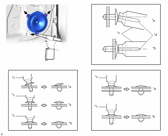
1. INSTALL FRONT NO. 1 SPEAKER ASSEMBLY
|
(a) Engage the claw and guide to temporarily install the front No. 1 speaker assembly. |
|
.png)
(b) Using an air riveter or a hand riveter, install the front No. 1 speaker assembly with 3 new rivets order show in the illustration.
|
*a |
Incorrect |
*b |
Correct |
|
*c |
Riveter |
*d |
Mandrel |
NOTICE:
- Do not touch the speaker cone.
- Do not pry on the rivets with the riveter, as this will cause damage to the riveter and mandrel.
- Confirm that the rivets are seated properly against the speaker.
- Do not tilt the riveter when installing the speaker with the rivets.
- Do not leave any space between the rivet heads and speaker.
- Do not leave any space between the speaker and door. Firmly hold the speaker and door together while installing the rivets.
HINT:
If the mandrel of the rivet does not come off on the first operation of the rivet gun, slide the rivet gun forward on the mandrel and operate it again.
(c) Connect the connector.
2. INSTALL FRONT DOOR TRIM BOARD SUB-ASSEMBLY
Click here
.gif)
3. INSTALL MULTIPLEX NETWORK MASTER SWITCH ASSEMBLY WITH FRONT ARMREST BASE UPPER PANEL (for Driver Side)
Click here
4. INSTALL POWER WINDOW REGULATOR SWITCH ASSEMBLY WITH FRONT ARMREST BASE UPPER PANEL (for Front Passenger Side)
Click here
5. INSTALL FRONT DOOR INSIDE HANDLE BEZEL PLUG
Click here
 Inspection
INSPECTION
PROCEDURE
1. INSPECT FRONT NO. 1 SPEAKER ASSEMBLY
(a) Check the resistance.
(1) Measure the resistance according to the value(s) in the table below.
Standard Resistance:
...

Other materials:
Toyota CH-R Service Manual > Lighting System: Terminals Of Ecu
TERMINALS OF ECU
*A
Main Body ECU (Multiplex Network Body ECU) with 1 Connector
-
-
*A
Main Body ECU (Multiplex Network Body ECU) with 2 Connectors
-
-
CHECK INSTRUMENT PANEL JUNCTION BLO ...
Toyota CH-R Service Manual > Power Window Control System: Remote Up / Down Function does not Operate
DESCRIPTION
When the ignition switch is ON, the multiplex network master switch assembly
sends remote up and down signals to each power window regulator motor assembly via
LIN communication.
WIRING DIAGRAM
CAUTION / NOTICE / HINT
NOTICE:
The power window control system uses the LI ...
Toyota C-HR (AX20) 2023-2026 Owner's Manual
Toyota CH-R Owners Manual
- For safety and security
- Instrument cluster
- Operation of each component
- Driving
- Interior features
- Maintenance and care
- When trouble arises
- Vehicle specifications
- For owners
Toyota CH-R Service Manual
- Introduction
- Maintenance
- Audio / Video
- Cellular Communication
- Navigation / Multi Info Display
- Park Assist / Monitoring
- Brake (front)
- Brake (rear)
- Brake Control / Dynamic Control Systems
- Brake System (other)
- Parking Brake
- Axle And Differential
- Drive Shaft / Propeller Shaft
- K114 Cvt
- 3zr-fae Battery / Charging
- Networking
- Power Distribution
- Power Assist Systems
- Steering Column
- Steering Gear / Linkage
- Alignment / Handling Diagnosis
- Front Suspension
- Rear Suspension
- Tire / Wheel
- Tire Pressure Monitoring
- Door / Hatch
- Exterior Panels / Trim
- Horn
- Lighting (ext)
- Mirror (ext)
- Window / Glass
- Wiper / Washer
- Door Lock
- Heating / Air Conditioning
- Interior Panels / Trim
- Lighting (int)
- Meter / Gauge / Display
- Mirror (int)
- Power Outlets (int)
- Pre-collision
- Seat
- Seat Belt
- Supplemental Restraint Systems
- Theft Deterrent / Keyless Entry

0.0073