Toyota CH-R Service Manual: Rear Side Marker Light Bulb
Components
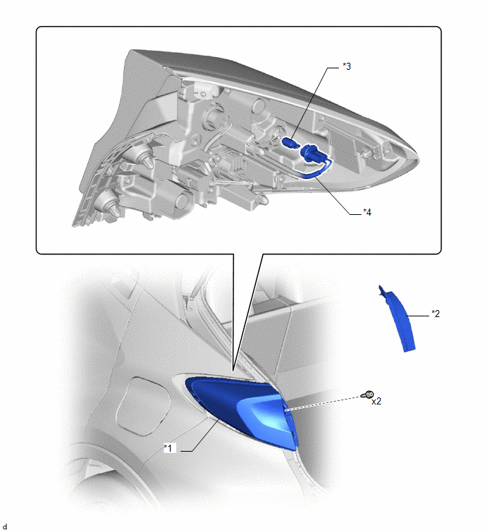
COMPONENTS
ILLUSTRATION
|
*1 |
REAR COMBINATION LIGHT ASSEMBLY |
*2 |
REAR COMBINATION LIGHT COVER |
|
*3 |
REAR SIDE MARKER LIGHT BULB |
*4 |
REAR COMBINATION LIGHT SOCKET AND WIRE |
Removal
REMOVAL
PROCEDURE
1. REMOVE REAR COMBINATION LIGHT COVER
Click here
.gif)
2. REMOVE REAR COMBINATION LIGHT ASSEMBLY
Click here
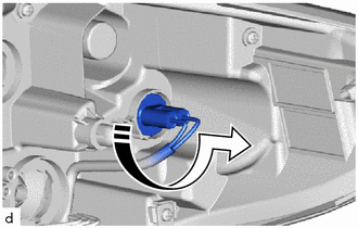
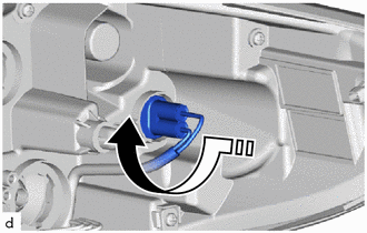
3. REMOVE REAR SIDE MARKER LIGHT BULB
(a) Turn the rear combination light socket and wire with the rear side marker light bulb as shown in the illustration to disconnect them as a unit.
.png) |
Remove in this Direction |
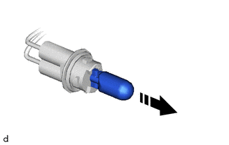
(b) Remove the rear side marker light bulb from the rear combination light socket and wire.
|
|
Remove in this Direction |
Installation
INSTALLATION
PROCEDURE
1. INSTALL REAR SIDE MARKER LIGHT BULB
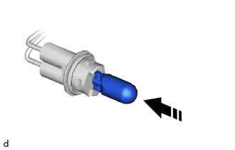
(a) Install the rear side marker light bulb to the rear combination light socket and wire.
.png) |
Install in this Direction |
(b) Turn the rear combination light socket and wire with the rear side marker light bulb as shown in the illustration to connect them as a unit.
|
|
Install in this Direction |
2. INSTALL REAR COMBINATION LIGHT ASSEMBLY
Click here
.gif)
3. INSTALL REAR COMBINATION LIGHT COVER
Click here
 Installation
INSTALLATION
CAUTION / NOTICE / HINT
NOTICE:
After replacing the rear disc brake pads, the brake pedal may feel soft due to
clearance between the rear disc brake pads and rear disc. Depress the b ...
 Rear Turn Signal Light Bulb
Components
COMPONENTS
ILLUSTRATION
*1
REAR COMBINATION LIGHT ASSEMBLY
*2
REAR COMBINATION LIGHT COVER
*3
REAR TURN SIGNAL ...
Other materials:
Toyota CH-R Service Manual > Automatic High Beam System: Lost Communication with Front Camera Module (U023A)
DESCRIPTION
This DTC is stored when the CAN communication system is malfunctioning.
DTC No.
Detection Item
DTC Detection Condition
Trouble Area
U023A
Lost Communication with Front Camera Module
Lost communication wi ...
Toyota CH-R Service Manual > Lighting System: Open in IG Circuit (B242E)
DESCRIPTION
This DTC is stored when a malfunction occurs in the headlight ECU sub-assembly
LH IG power source circuit. The headlight ECU sub-assembly LH stores DTC B242E.
DTC No.
Detection Item
DTC Detection Condition
Trouble Area
Note
...
Toyota C-HR (AX20) 2023-2026 Owner's Manual
Toyota CH-R Owners Manual
- For safety and security
- Instrument cluster
- Operation of each component
- Driving
- Interior features
- Maintenance and care
- When trouble arises
- Vehicle specifications
- For owners
Toyota CH-R Service Manual
- Introduction
- Maintenance
- Audio / Video
- Cellular Communication
- Navigation / Multi Info Display
- Park Assist / Monitoring
- Brake (front)
- Brake (rear)
- Brake Control / Dynamic Control Systems
- Brake System (other)
- Parking Brake
- Axle And Differential
- Drive Shaft / Propeller Shaft
- K114 Cvt
- 3zr-fae Battery / Charging
- Networking
- Power Distribution
- Power Assist Systems
- Steering Column
- Steering Gear / Linkage
- Alignment / Handling Diagnosis
- Front Suspension
- Rear Suspension
- Tire / Wheel
- Tire Pressure Monitoring
- Door / Hatch
- Exterior Panels / Trim
- Horn
- Lighting (ext)
- Mirror (ext)
- Window / Glass
- Wiper / Washer
- Door Lock
- Heating / Air Conditioning
- Interior Panels / Trim
- Lighting (int)
- Meter / Gauge / Display
- Mirror (int)
- Power Outlets (int)
- Pre-collision
- Seat
- Seat Belt
- Supplemental Restraint Systems
- Theft Deterrent / Keyless Entry

0.007