Toyota CH-R Service Manual: Components
COMPONENTS
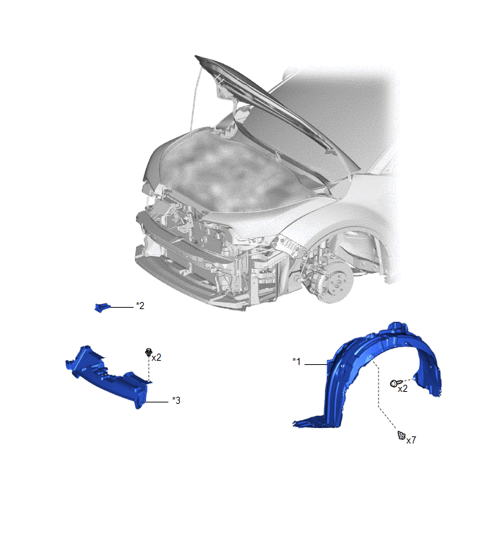
ILLUSTRATION
|
*1 |
FRONT FENDER LINER LH |
*2 |
NO. 1 RADIATOR GRILLE RETAINER |
|
*3 |
NO. 1 RADIATOR TO SUPPORT SEAL |
- |
- |
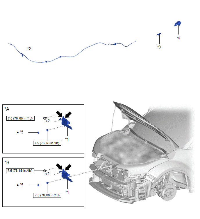
ILLUSTRATION
|
*A |
w/ Engine Hood Courtesy Switch |
*B |
w/o Engine Hood Courtesy Switch |
|
*1 |
HOOD LOCK ASSEMBLY |
*2 |
HOOD LOCK CONTROL CABLE ASSEMBLY |
|
*3 |
HOOD LOCK CONTROL CABLE HOLDER |
*4 |
HOOD LOCK CONTROL LEVER SUB-ASSEMBLY |
|
*5 |
HOOD LOCK NUT CAP |
- |
- |
.png) |
N*m (kgf*cm, ft.*lbf): Specified torque |
● |
Non-reusable part |
.png) |
MP grease |
- |
- |

 Removal
REMOVAL
PROCEDURE
1. REMOVE FRONT WHEEL
Click here
2. REMOVE FRONT BUMPER ASSEMBLY
Click here
3. REMOVE FRONT FENDER MOULDING SUB-ASSEMBLY
Click here
4. REMOVE ROCKER PANEL MOULDIN ...
Other materials:
Toyota CH-R Service Manual > Oil Cooler: Installation
INSTALLATION
PROCEDURE
1. INSTALL TRANSMISSION OIL COOLER BRACKET
(a) Install the transmission oil cooler bracket to the continuously variable
transaxle assembly with the 3 bolts in the order shown in the illustration.
Torque:
13.5 N·m {138 kgf·cm, 10 ft·lbf}
...
Toyota CH-R Service Manual > Rear Console Box: Installation
INSTALLATION
PROCEDURE
1. INSTALL REAR CONSOLE BOX ASSEMBLY
(a) Engage the guides to install the rear console box assembly as shown in the
illustration.
Install in this Direction
(b) Connect the connector.
(c) Install the 4 bolts.
(d) Install the 4 screws.
2. ...
Toyota C-HR (AX20) 2023-2026 Owner's Manual
Toyota CH-R Owners Manual
- For safety and security
- Instrument cluster
- Operation of each component
- Driving
- Interior features
- Maintenance and care
- When trouble arises
- Vehicle specifications
- For owners
Toyota CH-R Service Manual
- Introduction
- Maintenance
- Audio / Video
- Cellular Communication
- Navigation / Multi Info Display
- Park Assist / Monitoring
- Brake (front)
- Brake (rear)
- Brake Control / Dynamic Control Systems
- Brake System (other)
- Parking Brake
- Axle And Differential
- Drive Shaft / Propeller Shaft
- K114 Cvt
- 3zr-fae Battery / Charging
- Networking
- Power Distribution
- Power Assist Systems
- Steering Column
- Steering Gear / Linkage
- Alignment / Handling Diagnosis
- Front Suspension
- Rear Suspension
- Tire / Wheel
- Tire Pressure Monitoring
- Door / Hatch
- Exterior Panels / Trim
- Horn
- Lighting (ext)
- Mirror (ext)
- Window / Glass
- Wiper / Washer
- Door Lock
- Heating / Air Conditioning
- Interior Panels / Trim
- Lighting (int)
- Meter / Gauge / Display
- Mirror (int)
- Power Outlets (int)
- Pre-collision
- Seat
- Seat Belt
- Supplemental Restraint Systems
- Theft Deterrent / Keyless Entry

0.0081