Toyota CH-R Service Manual: Removal
REMOVAL
PROCEDURE
1. REMOVE FRONT WHEEL
Click here
.gif)
2. REMOVE FRONT BUMPER ASSEMBLY
Click here
3. REMOVE FRONT FENDER MOULDING SUB-ASSEMBLY
Click here
4. REMOVE ROCKER PANEL MOULDING LH
Click here
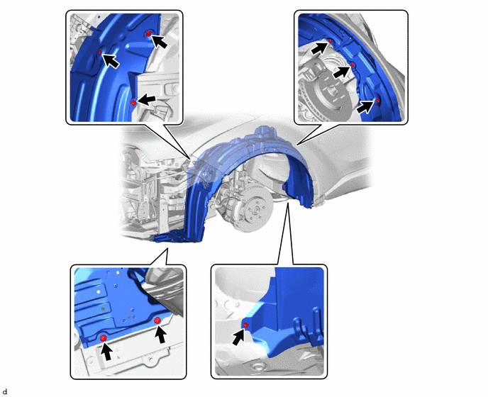
5. REMOVE FRONT FENDER LINER LH
(a) Remove the 2 screws, 7 clips and front fender liner LH.
6. REMOVE NO. 1 RADIATOR GRILLE RETAINER
Click here
7. REMOVE NO. 1 RADIATOR TO SUPPORT SEAL
Click here
8. REMOVE HOOD LOCK NUT CAP
Click here
9. REMOVE HOOD LOCK ASSEMBLY (w/ Engine Hood Courtesy Switch)
Click here
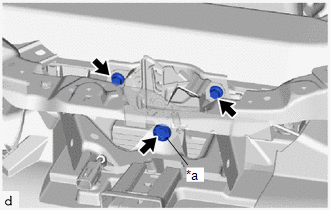
10. REMOVE HOOD LOCK ASSEMBLY (w/o Engine Hood Courtesy Switch)
|
(a) Remove the 2 bolts and hood lock bolt. |
|
|
(b) Disengage the guide to remove the hood lock assembly from the hood lock control cable assembly. |
|
11. DISCONNECT HOOD LOCK CONTROL LEVER SUB-ASSEMBLY
Click here
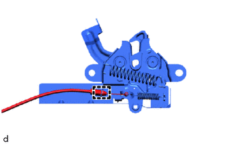
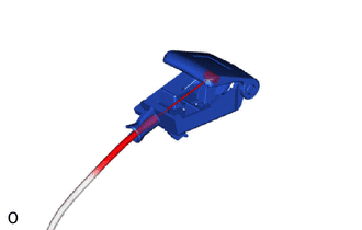
12. REMOVE HOOD LOCK CONTROL CABLE HOLDER
(a) Disengage the claw to remove the hood lock control cable holder as shown in the illustration.
.png) |
Remove in this Direction |
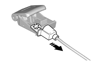
13. REMOVE HOOD LOCK CONTROL LEVER SUB-ASSEMBLY
|
(a) Remove the hood lock control lever sub-assembly from the hood lock control cable assembly. |
|
14. REMOVE HOOD LOCK CONTROL CABLE ASSEMBLY
(a) Disconnect the hood lock control cable assembly from the clamps.
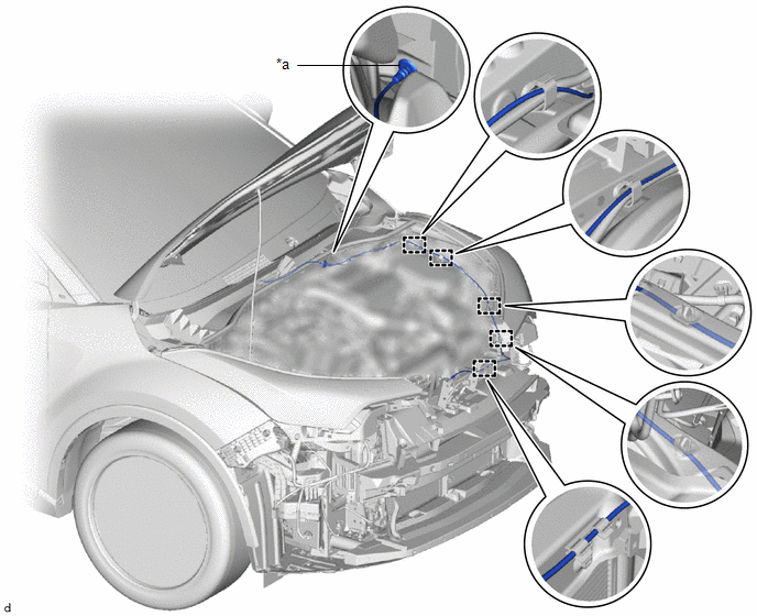
|
*a |
Grommet |
- |
- |
(b) Disengage the grommet.
(c) Pull the hood lock control cable assembly from the engine compartment to remove it.
 Components
COMPONENTS
ILLUSTRATION
*1
FRONT FENDER LINER LH
*2
NO. 1 RADIATOR GRILLE RETAINER
*3
NO. 1 RADIATOR TO SUPPORT SEAL
...
 Installation
INSTALLATION
PROCEDURE
1. INSTALL HOOD LOCK CONTROL CABLE ASSEMBLY
(a) Pass the hood lock control cable assembly into the engine compartment.
(b) Engage the grommet.
*a
Gr ...
Other materials:
Toyota CH-R Service Manual > Blind Spot Monitor System: How To Proceed With Troubleshooting
CAUTION / NOTICE / HINT
HINT:
Use the following procedure to troubleshoot the blind spot monitor system.
*: Use the Techstream.
PROCEDURE
1.
VEHICLE BROUGHT TO WORKSHOP
NEXT
...
Toyota CH-R Service Manual > Occupant Detection Sensor: Inspection
INSPECTION
PROCEDURE
1. INSPECT OCCUPANT DETECTION SENSOR (SEPARATE TYPE FRONT SEAT CUSHION PAD)
(a) Check the resistance.
(1) Measure the resistance according to the value(s) in the table below.
Standard Resistance:
Tester Connection
Condition ...
Toyota C-HR (AX20) 2023-2026 Owner's Manual
Toyota CH-R Owners Manual
- For safety and security
- Instrument cluster
- Operation of each component
- Driving
- Interior features
- Maintenance and care
- When trouble arises
- Vehicle specifications
- For owners
Toyota CH-R Service Manual
- Introduction
- Maintenance
- Audio / Video
- Cellular Communication
- Navigation / Multi Info Display
- Park Assist / Monitoring
- Brake (front)
- Brake (rear)
- Brake Control / Dynamic Control Systems
- Brake System (other)
- Parking Brake
- Axle And Differential
- Drive Shaft / Propeller Shaft
- K114 Cvt
- 3zr-fae Battery / Charging
- Networking
- Power Distribution
- Power Assist Systems
- Steering Column
- Steering Gear / Linkage
- Alignment / Handling Diagnosis
- Front Suspension
- Rear Suspension
- Tire / Wheel
- Tire Pressure Monitoring
- Door / Hatch
- Exterior Panels / Trim
- Horn
- Lighting (ext)
- Mirror (ext)
- Window / Glass
- Wiper / Washer
- Door Lock
- Heating / Air Conditioning
- Interior Panels / Trim
- Lighting (int)
- Meter / Gauge / Display
- Mirror (int)
- Power Outlets (int)
- Pre-collision
- Seat
- Seat Belt
- Supplemental Restraint Systems
- Theft Deterrent / Keyless Entry

0.0071