Toyota CH-R Service Manual: Installation
INSTALLATION
PROCEDURE
1. INSTALL HOOD LOCK CONTROL CABLE ASSEMBLY
(a) Pass the hood lock control cable assembly into the engine compartment.
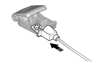
(b) Engage the grommet.
.png)
|
*a |
Grommet |
- |
- |
(c) Connect the hood lock control cable assembly to the clamps.
2. INSTALL HOOD LOCK CONTROL LEVER SUB-ASSEMBLY
(a) Install the hood lock control lever sub-assembly to the hood lock control cable assembly.
3. INSTALL HOOD LOCK CONTROL CABLE HOLDER
(a) Engage the claw to install the hood lock control cable holder as shown in the illustration.
.png) |
Install in this Direction |
4. CONNECT HOOD LOCK CONTROL LEVER SUB-ASSEMBLY
Click here
.gif)
5. INSTALL HOOD LOCK ASSEMBLY (w/o Engine Hood Courtesy Switch)
(a) Apply MP grease to the sliding areas of the hood lock assembly.
(b) Connect the hood lock control cable assembly to the hood lock assembly.
(c) Install the hood lock assembly with the 2 bolts and hood lock bolt.
Torque:
7.5 N·m {76 kgf·cm, 66 in·lbf}
6. INSTALL HOOD LOCK ASSEMBLY (w/ Engine Hood Courtesy Switch)
Click here
7. INSTALL HOOD LOCK NUT CAP
Click here
8. INSTALL NO. 1 RADIATOR TO SUPPORT SEAL
Click here
9. INSTALL NO. 1 RADIATOR GRILLE RETAINER
Click here
10. INSTALL FRONT FENDER LINER LH
(a) Install the front fender liner LH with the 7 clips and 2 screws.
11. INSTALL ROCKER PANEL MOULDING LH
Click here
12. INSTALL FRONT FENDER MOULDING SUB-ASSEMBLY
Click here
13. INSTALL FRONT BUMPER ASSEMBLY
Click here
14. INSTALL FRONT WHEEL
Click here
15. ADJUST HOOD SUB-ASSEMBLY
Click here
 Removal
REMOVAL
PROCEDURE
1. REMOVE FRONT WHEEL
Click here
2. REMOVE FRONT BUMPER ASSEMBLY
Click here
3. REMOVE FRONT FENDER MOULDING SUB-ASSEMBLY
Click here
4. REMOVE ROCKER PANEL MOULDIN ...
 Rear Door
...
Other materials:
Toyota CH-R Service Manual > Air Conditioning System(for Automatic Air Conditioning System With Top-mounted
Air Conditioner Pressure Sensor): Ambient Temperature Sensor Circuit (B1412)
DESCRIPTION
The thermistor assembly is installed in front of the cooler condenser assembly
to detect the ambient temperature, which is used to control the air conditioning
system. This sensor is connected to the combination meter assembly and detects fluctuations
in the ambient temperature. T ...
Toyota CH-R Service Manual > Airbag System: Vehicle Control History
VEHICLE CONTROL HISTORY
Function Overview
(a) The vehicle control history is a function that records control data (record
data) when triggered by specific vehicle behavior. When DTCs are not detected according
to information provided by customers, by checking the vehicle control history, it
...
Toyota C-HR (AX20) 2023-2026 Owner's Manual
Toyota CH-R Owners Manual
- For safety and security
- Instrument cluster
- Operation of each component
- Driving
- Interior features
- Maintenance and care
- When trouble arises
- Vehicle specifications
- For owners
Toyota CH-R Service Manual
- Introduction
- Maintenance
- Audio / Video
- Cellular Communication
- Navigation / Multi Info Display
- Park Assist / Monitoring
- Brake (front)
- Brake (rear)
- Brake Control / Dynamic Control Systems
- Brake System (other)
- Parking Brake
- Axle And Differential
- Drive Shaft / Propeller Shaft
- K114 Cvt
- 3zr-fae Battery / Charging
- Networking
- Power Distribution
- Power Assist Systems
- Steering Column
- Steering Gear / Linkage
- Alignment / Handling Diagnosis
- Front Suspension
- Rear Suspension
- Tire / Wheel
- Tire Pressure Monitoring
- Door / Hatch
- Exterior Panels / Trim
- Horn
- Lighting (ext)
- Mirror (ext)
- Window / Glass
- Wiper / Washer
- Door Lock
- Heating / Air Conditioning
- Interior Panels / Trim
- Lighting (int)
- Meter / Gauge / Display
- Mirror (int)
- Power Outlets (int)
- Pre-collision
- Seat
- Seat Belt
- Supplemental Restraint Systems
- Theft Deterrent / Keyless Entry

0.0074