
Toyota CH-R Service Manual: Components
COMPONENTS
ILLUSTRATION
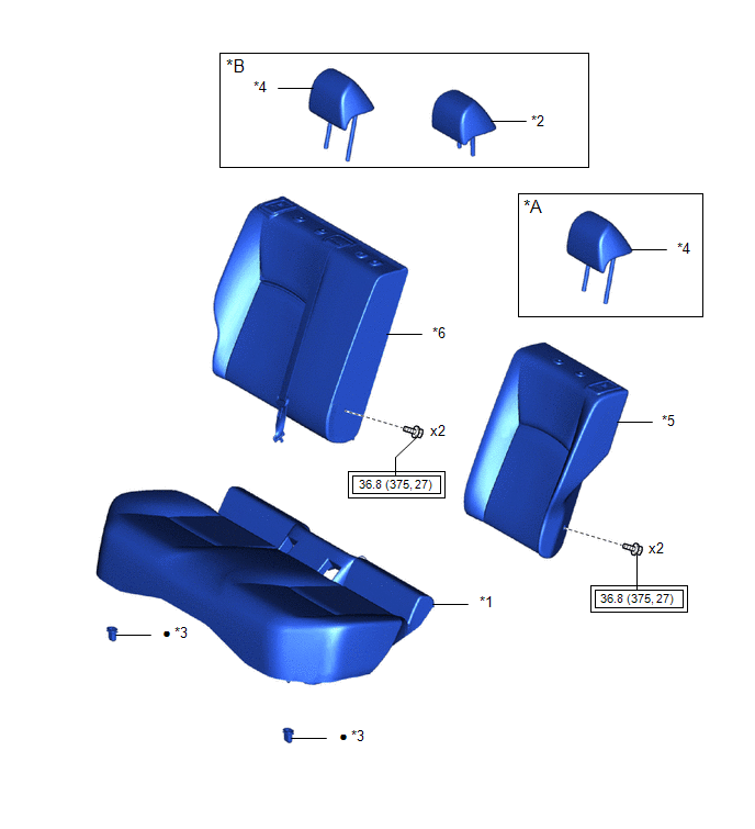
|
*A |
for LH Side |
*B |
for RH Side |
|
*1 |
BENCH TYPE REAR SEAT CUSHION ASSEMBLY |
*2 |
REAR SEAT CENTER HEADREST ASSEMBLY |
|
*3 |
REAR SEAT CUSHION LOCK HOOK |
*4 |
REAR SEAT HEADREST ASSEMBLY |
|
*5 |
REAR SEATBACK ASSEMBLY LH |
*6 |
REAR SEATBACK ASSEMBLY RH |
.png) |
Tightening torque for "Major areas involving basic vehicle performance such as moving/turning/stopping" : N*m (kgf*cm, ft.*lbf) |
● |
Non-reusable part |
ILLUSTRATION
|
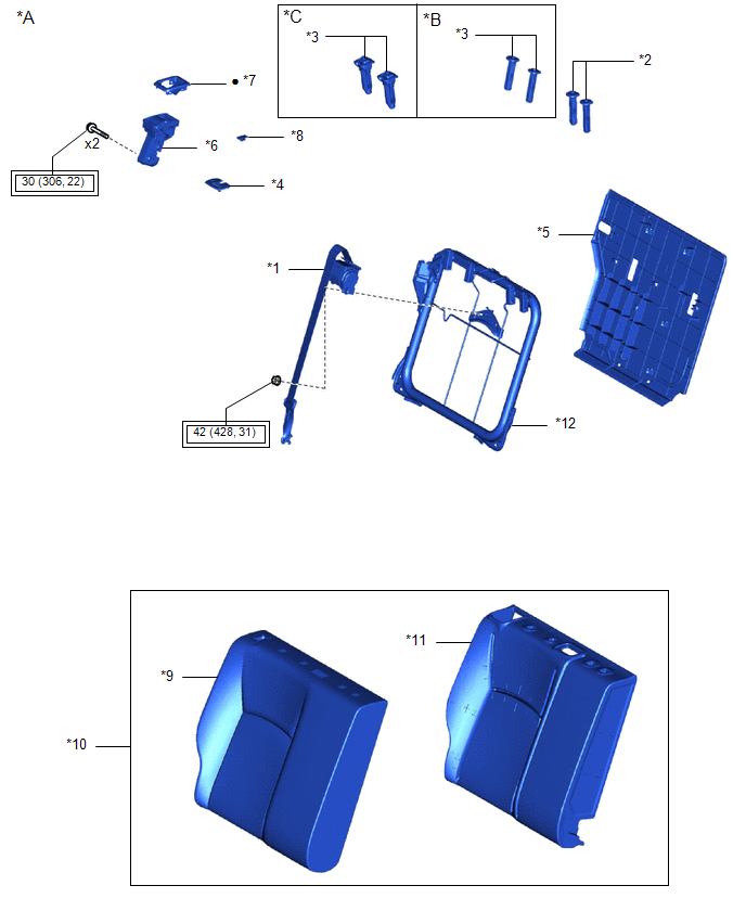
*A |
for RH Side |
*B |
w/o Occupant Classification System |
|
*C |
w/ Occupant Classification System |
- |
- |
|
*1 |
REAR CENTER SEAT OUTER BELT ASSEMBLY |
*2 |
REAR SEAT CENTER HEADREST SUPPORT |
|
*3 |
REAR SEAT HEADREST SUPPORT |
*4 |
REAR SEAT SHOULDER BELT HOLE COVER |
|
*5 |
REAR SEATBACK BOARD SUB-ASSEMBLY RH |
*6 |
REAR SEATBACK LOCK ASSEMBLY RH |
|
*7 |
REAR SEATBACK LOCK CONTROL BEZEL |
*8 |
SEAT BELT ANCHOR COVER CAP |
|
*9 |
SEPARATE TYPE REAR SEATBACK COVER |
*10 |
SEPARATE TYPE REAR SEATBACK COVER WITH PAD |
|
*11 |
SEPARATE TYPE REAR SEATBACK PAD RH |
*12 |
REAR SEAT BACK FRAME SUB-ASSEMBLY RH |
|
|
Tightening torque for "Major areas involving basic vehicle performance such as moving/turning/stopping" : N*m (kgf*cm, ft.*lbf) |
● |
Non-reusable part |
ILLUSTRATION
|
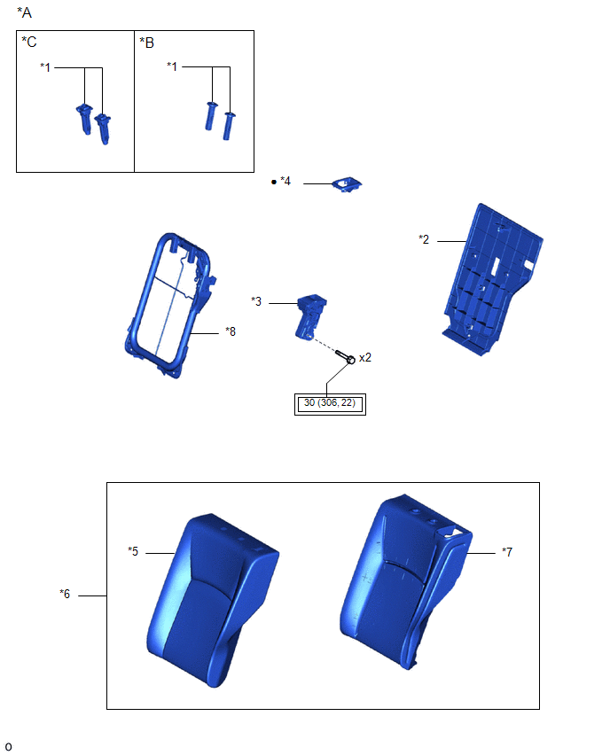
*A |
for LH Side |
*B |
w/o Occupant Classification System |
|
*C |
w/ Occupant Classification System |
- |
- |
|
*1 |
REAR SEAT HEADREST SUPPORT |
*2 |
REAR SEATBACK BOARD SUB-ASSEMBLY LH |
|
*3 |
REAR SEATBACK LOCK ASSEMBLY LH |
*4 |
REAR SEATBACK LOCK CONTROL BEZEL |
|
*5 |
SEPARATE TYPE REAR SEATBACK COVER |
*6 |
SEPARATE TYPE REAR SEATBACK COVER WITH PAD |
|
*7 |
SEPARATE TYPE REAR SEATBACK PAD LH |
*8 |
REAR SEAT BACK FRAME SUB-ASSEMBLY LH |
|
|
Tightening torque for "Major areas involving basic vehicle performance such as moving/turning/stopping" : N*m (kgf*cm, ft.*lbf) |
● |
Non-reusable part |
ILLUSTRATION
|
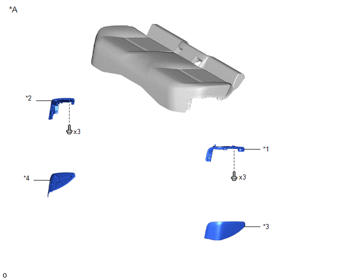
*A |
w/ Occupant Classification System |
- |
- |
|
*1 |
REAR NO. 2 SEAT COVER BEZEL |
*2 |
REAR NO. 1 SEAT COVER BEZEL |
|
*3 |
REAR DOOR SCUFF PANEL LH |
*4 |
REAR DOOR SCUFF PANEL RH |
ILLUSTRATION
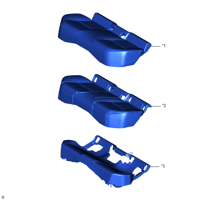
|
*1 |
BENCH TYPE REAR SEAT CUSHION COVER |
*2 |
NO. 1 REAR SEAT CUSHION PAD SUB-ASSEMBLY |
|
*3 |
REAR SEAT CUSHION PAD |
- |
- |

 Removal
REMOVAL
CAUTION / NOTICE / HINT
CAUTION:
Wear protective gloves. Sharp areas on the parts may injure your hands.
PROCEDURE
1. REMOVE REAR SEAT HEADREST ASSEMBLY (for RH Side)
(a) Remove the rear ...
Other materials:
Toyota CH-R Service Manual > Window Defogger System: Terminals Of Ecu
TERMINALS OF ECU
CHECK AIR CONDITIONING AMPLIFIER ASSEMBLY (for TMMT Made)
(a) Disconnect the F72 air conditioning amplifier assembly connector.
(b) Measure the voltage and resistance according to the value(s) in the table
below.
HINT:
Measure the values on the wire harness side with the co ...
Toyota CH-R Service Manual > Air Conditioning System(for Automatic Air Conditioning System With Top-mounted
Air Conditioner Pressure Sensor): Ambient Temperature Display System
DESCRIPTION
The outside temperature sensor is installed in front of the cooler condenser
assembly to detect the ambient temperature which is used to control the air conditioning
system AUTO mode. This sensor is connected to the combination meter assembly and
detects fluctuations in the ambien ...
Toyota C-HR (AX20) 2023-2026 Owner's Manual
Toyota CH-R Owners Manual
- For safety and security
- Instrument cluster
- Operation of each component
- Driving
- Interior features
- Maintenance and care
- When trouble arises
- Vehicle specifications
- For owners
Toyota CH-R Service Manual
- Introduction
- Maintenance
- Audio / Video
- Cellular Communication
- Navigation / Multi Info Display
- Park Assist / Monitoring
- Brake (front)
- Brake (rear)
- Brake Control / Dynamic Control Systems
- Brake System (other)
- Parking Brake
- Axle And Differential
- Drive Shaft / Propeller Shaft
- K114 Cvt
- 3zr-fae Battery / Charging
- Networking
- Power Distribution
- Power Assist Systems
- Steering Column
- Steering Gear / Linkage
- Alignment / Handling Diagnosis
- Front Suspension
- Rear Suspension
- Tire / Wheel
- Tire Pressure Monitoring
- Door / Hatch
- Exterior Panels / Trim
- Horn
- Lighting (ext)
- Mirror (ext)
- Window / Glass
- Wiper / Washer
- Door Lock
- Heating / Air Conditioning
- Interior Panels / Trim
- Lighting (int)
- Meter / Gauge / Display
- Mirror (int)
- Power Outlets (int)
- Pre-collision
- Seat
- Seat Belt
- Supplemental Restraint Systems
- Theft Deterrent / Keyless Entry

0.0103