Toyota CH-R Service Manual: Passenger Side Buckle Switch Circuit Malfunction (B1771)
DESCRIPTION
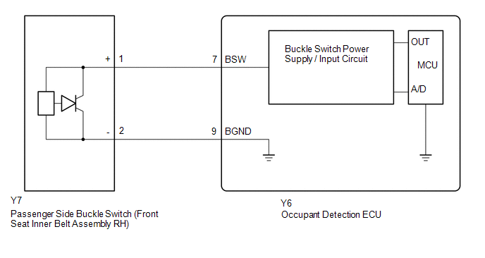
The passenger side buckle switch circuit consists of the occupant detection ECU and passenger side buckle switch (front seat inner belt assembly RH).
DTC B1771 is stored when a malfunction is detected in the passenger side buckle switch circuit.
|
DTC No. |
Detection Item |
DTC Detection Condition |
Trouble Area |
|---|---|---|---|
|
B1771 |
Passenger Side Buckle Switch Circuit Malfunction |
Any of the following conditions is met:
|
|
|
Vehicle Condition |
|||||||
|---|---|---|---|---|---|---|---|
|
Pattern 1 |
Pattern 2 |
Pattern 3 |
Pattern 4 |
Pattern 5 |
Pattern 6 |
||
|
Diagnosis Condition |
Ignition switch ON |
○ |
○ |
○ |
○ |
○ |
○ |
|
Malfunction Status |
The occupant detection ECU detects a line short in the passenger side buckle switch circuit. |
○ |
- |
- |
- |
- |
- |
|
The occupant detection ECU detects a line short to ground in the passenger side buckle switch circuit. |
- |
○ |
- |
- |
- |
- |
|
|
The occupant detection ECU detects a line short to B+ in the passenger side buckle switch circuit. |
- |
- |
○ |
- |
- |
- |
|
|
The occupant detection ECU detects an line open in the passenger side buckle switch circuit. |
- |
- |
- |
○ |
- |
- |
|
|
Passenger side buckle switch malfunction |
- |
- |
- |
- |
○ |
- |
|
|
Occupant detection ECU malfunction |
- |
- |
- |
- |
- |
○ |
|
|
Detection Time |
- |
- |
- |
- |
- |
- |
|
|
Number of Trips |
1 trip |
1 trip |
1 trip |
1 trip |
1 trip |
1 trip |
|
HINT:
DTC will be output when conditions for either of the patterns in the table above are met.
WIRING DIAGRAM
CAUTION / NOTICE / HINT
NOTICE:
After turning the ignition switch off, waiting time may be required before disconnecting the cable from the negative (-) battery terminal. Therefore, make sure to read the disconnecting the cable from the negative (-) battery terminal notices before proceeding with work.
Click here .gif)
HINT:
- When DTC B1650/32 is stored as a result of troubleshooting for the airbag system, check the DTCs stored in the occupant detection ECU. When DTC B1771 is output, perform troubleshooting for this DTC first.
- If it is difficult to perform troubleshooting (wire harness inspection), remove the front passenger seat installation bolts to see under the seat cushion.
- In the above case, lift and hold the seat so that it does not fall down. Hold the seat only as necessary because holding the seat for a long period of time may cause seat rail deformation.
PROCEDURE
|
1. |
CHECK CONNECTORS |
(a) Turn the ignition switch off.
(b) Disconnect the cable from the negative (-) battery terminal.
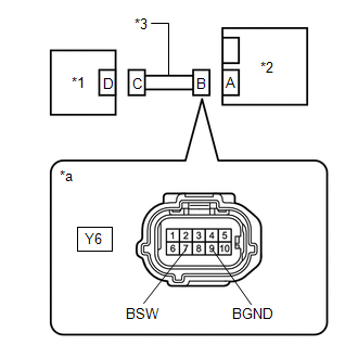
(c) Check that the connectors are properly connected to the occupant detection ECU and front seat inner belt assembly RH.
OK:
The connectors are properly connected.
HINT:
If the connectors are not properly connected, reconnect the connectors and proceed to the next inspection.
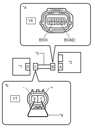
(d) Disconnect the connectors from the occupant detection ECU and front seat inner belt assembly RH.
(e) Check that the terminals of the connectors are not deformed or damaged.
OK:
The terminals are not deformed or damaged.
| NG | .gif) |
REPLACE FRONT SEAT WIRE RH |
|
.gif)
|
2. |
CHECK FRONT SEAT WIRE RH (SHORT TO B+) |
|
(a) Connect the cable to the negative (-) battery terminal. |
|
(b) Turn the ignition switch to ON.
(c) Measure the voltage according to the value(s) in the table below.
Standard Voltage:
|
Tester Connection |
Switch Condition |
Specified Condition |
|---|---|---|
|
Y6-7 (BSW) - Body ground |
Ignition switch ON |
Below 1 V |
|
Y6-9 (BGND) - Body ground |
Ignition switch ON |
Below 1 V |
(d) Turn the ignition switch off.
(e) Disconnect the cable from the negative (-) battery terminal.
| NG | |
REPLACE FRONT SEAT WIRE RH |
|
|
3. |
CHECK FRONT SEAT WIRE RH (OPEN) |
|
(a) Using a service wire, connect terminals 1 (+) and 2 (-) of connector C. NOTICE: Do not forcibly insert the service wire into the terminals of the connector when connecting the wire. |
|
(b) Measure the resistance according to the value(s) in the table below.
Standard Resistance:
|
Tester Connection |
Condition |
Specified Condition |
|---|---|---|
|
Y6-7 (BSW) - Y6-9 (BGND) |
Always |
Below 1 Ω |
(c) Disconnect the service wire from connector C.
| NG | |
REPLACE FRONT SEAT WIRE RH |
|
|
4. |
CHECK FRONT SEAT WIRE RH (SHORT) |
|
(a) Measure the resistance according to the value(s) in the table below. Standard Resistance:
|
|
| NG | |
REPLACE FRONT SEAT WIRE RH |
|
|
5. |
CHECK FRONT SEAT WIRE RH (SHORT TO GROUND) |
|
(a) Measure the resistance according to the value(s) in the table below. Standard Resistance:
|
|
| NG | |
REPLACE FRONT SEAT WIRE RH |
|
|
6. |
CHECK DTC |
(a) Connect the connectors to the occupant detection ECU and front seat inner belt assembly RH.
(b) Connect the cable to the negative (-) battery terminal.
(c) Clear the DTCs stored in the occupant detection ECU.
Click here
(d) Clear the DTCs stored in the airbag sensor assembly.
Click here
(e) Turn the ignition switch off.
(f) Turn the ignition switch to ON, and wait for at least 10 seconds.
(g) Check for DTCs.
Click here
OK:
DTC B1771 is not output.
HINT:
Codes other than DTC B1771 may be output at this time, but they are not related to this check.
(h) Turn the ignition switch off.
| OK | |
USE SIMULATION METHOD TO CHECK |
|
|
7. |
CHECK FRONT SEAT INNER BELT ASSEMBLY RH |
(a) Disconnect the cable from the negative (-) battery terminal.
(b) Replace the front seat inner belt assembly RH with a known good one.
Click here
HINT:
Perform the following inspection using known good parts from another vehicle if possible.
(c) Connect the cable to the negative (-) battery terminal.
(d) Clear the DTCs stored in the occupant detection ECU.
Click here
(e) Clear the DTCs stored in the airbag sensor assembly.
Click here
(f) Turn the ignition switch off.
(g) Turn the ignition switch to ON, and wait for at least 10 seconds.
(h) Check for DTCs.
Click here
OK:
DTC B1771 is not output.
HINT:
Codes other than DTC B1771 may be output at this time, but they are not related to this check.
(i) Turn the ignition switch off.
(j) Disconnect the cable from the negative (-) battery terminal.
(k) Restore the front seat inner belt assembly RH that was installed for testing to its original location.
Click here
| OK | |
REPLACE FRONT SEAT INNER BELT ASSEMBLY RH
|
|
|
8. |
REPLACE OCCUPANT DETECTION ECU |
(a) Turn the ignition switch off.
(b) Disconnect the cable from the negative (-) battery terminal.
(c) Replace the occupant detection ECU with a new one.
Click here
(d) Connect the cable to the negative (-) battery terminal.
|
|
9. |
PERFORM ZERO POINT CALIBRATION |
(a) Using the Techstream, perform Zero Point Calibration.
Click here
|
Tester Display |
|---|
|
Zero Point Calibration |
| NEXT | |
END |
 Front Occupant Classification Sensor LH Circuit Malfunction (B1780)
DESCRIPTION
The front occupant classification sensor LH circuit consists of the occupant
detection ECU and front in weight detection sensor sub-assembly.
DTC B1780 is stored when a malfunction is ...
 Trouble in Passenger Airbag ON/OFF Indicator
DESCRIPTION
The occupant classification system detects the front passenger seat condition.
It then displays the instrument panel passenger airbag assembly and front seat cushion
airbag assembly R ...
Other materials:
Toyota CH-R Service Manual > Smart Key System(for Entry Function): How To Proceed With Troubleshooting
CAUTION / NOTICE / HINT
HINT:
Use these procedures to troubleshoot the smart key system (for Entry
Function).
*: Use the Techstream.
PROCEDURE
1.
VEHICLE BROUGHT TO WORKSHOP
NEXT
...
Toyota CH-R Owners Manual > Using the storage features: List of storage features
Glove box
Bottle holders
Cup holders
Console box
WARNING
Do not leave glasses, lighters or spray cans in the storage spaces,
as this may cause the following when cabin temperature becomes high:
Glasses may be deformed by heat or cracked if they come into contact
w ...
Toyota C-HR (AX20) 2023-2026 Owner's Manual
Toyota CH-R Owners Manual
- For safety and security
- Instrument cluster
- Operation of each component
- Driving
- Interior features
- Maintenance and care
- When trouble arises
- Vehicle specifications
- For owners
Toyota CH-R Service Manual
- Introduction
- Maintenance
- Audio / Video
- Cellular Communication
- Navigation / Multi Info Display
- Park Assist / Monitoring
- Brake (front)
- Brake (rear)
- Brake Control / Dynamic Control Systems
- Brake System (other)
- Parking Brake
- Axle And Differential
- Drive Shaft / Propeller Shaft
- K114 Cvt
- 3zr-fae Battery / Charging
- Networking
- Power Distribution
- Power Assist Systems
- Steering Column
- Steering Gear / Linkage
- Alignment / Handling Diagnosis
- Front Suspension
- Rear Suspension
- Tire / Wheel
- Tire Pressure Monitoring
- Door / Hatch
- Exterior Panels / Trim
- Horn
- Lighting (ext)
- Mirror (ext)
- Window / Glass
- Wiper / Washer
- Door Lock
- Heating / Air Conditioning
- Interior Panels / Trim
- Lighting (int)
- Meter / Gauge / Display
- Mirror (int)
- Power Outlets (int)
- Pre-collision
- Seat
- Seat Belt
- Supplemental Restraint Systems
- Theft Deterrent / Keyless Entry

0.0101