Toyota CH-R Service Manual: Front Occupant Classification Sensor LH Circuit Malfunction (B1780)
DESCRIPTION
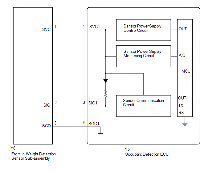
The front occupant classification sensor LH circuit consists of the occupant detection ECU and front in weight detection sensor sub-assembly.
DTC B1780 is stored when a malfunction is detected in the front in weight detection sensor sub-assembly circuit.
|
DTC No. |
Detection Item |
DTC Detection Condition |
Trouble Area |
|---|---|---|---|
|
B1780 |
Front Occupant Classification Sensor LH Circuit Malfunction |
Any of the following conditions is met:
|
|
- *: The front in weight detection sensor sub-assembly is built into the front seat adjuster assembly RH.
|
Vehicle Condition |
|||||||
|---|---|---|---|---|---|---|---|
|
Pattern 1 |
Pattern 2 |
Pattern 3 |
Pattern 4 |
Pattern 5 |
Pattern 6 |
||
|
Diagnosis Condition |
Ignition switch ON |
○ |
○ |
○ |
○ |
○ |
○ |
|
Malfunction Status |
The occupant detection ECU detects a line short in the front in weight detection sensor sub-assembly circuit. |
○ |
- |
- |
- |
- |
- |
|
The occupant detection ECU detects a line short to ground in the front in weight detection sensor sub-assembly circuit. |
- |
○ |
- |
- |
- |
- |
|
|
The occupant detection ECU detects a line short to B+ in the front in weight detection sensor sub-assembly circuit. |
- |
- |
○ |
- |
- |
- |
|
|
The occupant detection ECU detects a line open in the front in weight detection sensor sub-assembly circuit. |
- |
- |
- |
○ |
- |
- |
|
|
Front in weight detection sensor sub-assembly malfunction |
- |
- |
- |
- |
○ |
- |
|
|
Occupant detection ECU malfunction |
- |
- |
- |
- |
- |
○ |
|
|
Detection Time |
- |
- |
- |
- |
- |
- |
|
|
Number of Trips |
1 trip |
1 trip |
1 trip |
1 trip |
1 trip |
1 trip |
|
HINT:
DTC will be output when conditions for either of the patterns in the table above are met.
WIRING DIAGRAM
CAUTION / NOTICE / HINT
NOTICE:
After turning the ignition switch off, waiting time may be required before disconnecting the cable from the negative (-) battery terminal. Therefore, make sure to read the disconnecting the cable from the negative (-) battery terminal notices before proceeding with work.
Click here .gif)
HINT:
- When DTC B1650/32 is stored as a result of troubleshooting for the airbag system, check the DTCs stored in the occupant detection ECU. When DTC B1780 is output, perform troubleshooting for this DTC first.
- If it is difficult to perform troubleshooting (wire harness inspection), remove the front passenger seat installation bolts to see under the seat cushion.
- In the above case, lift and hold the seat so that it does not fall down. Hold the seat only as necessary because holding the seat for a long period of time may cause seat rail deformation.
PROCEDURE
|
1. |
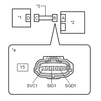
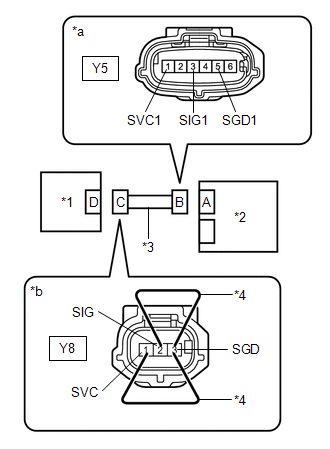
CHECK CONNECTORS |
(a) Turn the ignition switch off.
(b) Disconnect the cable from the negative (-) battery terminal.
(c) Check that the connectors are properly connected to the occupant detection ECU and front in weight detection sensor sub-assembly.
OK:
The connectors are properly connected.
HINT:
If the connectors are not properly connected, reconnect the connectors and proceed to the next inspection.
(d) Disconnect the connectors from the occupant detection ECU and front in weight detection sensor sub-assembly.
(e) Check that the terminals of the connectors are not deformed or damaged.
OK:
The terminals are not deformed or damaged.
| NG | .gif) |
REPLACE FRONT SEAT WIRE RH |
|
.gif)
|
2. |
CHECK FRONT SEAT WIRE RH (SHORT TO B+) |
|
(a) Connect the cable to the negative (-) battery terminal. |
|
(b) Turn the ignition switch to ON.
(c) Measure the voltage according to the value(s) in the table below.
Standard Voltage:
|
Tester Connection |
Switch Condition |
Specified Condition |
|---|---|---|
|
Y5-1 (SVC1) - Body ground |
Ignition switch ON |
Below 1 V |
|
Y5-3 (SIG1) - Body ground |
Ignition switch ON |
Below 1 V |
|
Y5-5 (SGD1) - Body ground |
Ignition switch ON |
Below 1 V |
(d) Turn the ignition switch off.
(e) Disconnect the cable from the negative (-) battery terminal.
| NG | |
GO TO STEP 12 |
|
|
3. |
CHECK FRONT SEAT WIRE RH (OPEN) |
|
(a) Using service wires, connect terminals 1 (SVC) and 3 (SGD), and terminals 2 (SIG) and 3 (SGD) of connector C. NOTICE: Do not forcibly insert the service wire into the terminals of the connector when connecting the wire. |
|
(b) Measure the resistance according to the value(s) in the table below.
Standard Resistance:
|
Tester Connection |
Condition |
Specified Condition |
|---|---|---|
|
Y5-1 (SVC1) - Y5-5 (SGD1) |
Always |
Below 1 Ω |
|
Y5-3 (SIG1) - Y5-5 (SGD1) |
Always |
Below 1 Ω |
(c) Disconnect the service wires from connector C.
| NG | |
REPLACE FRONT SEAT WIRE RH |
|
|
4. |
CHECK FRONT SEAT WIRE RH (SHORT) |
|
(a) Measure the resistance according to the value(s) in the table below. Standard Resistance:
|
|
| NG | |
REPLACE FRONT SEAT WIRE RH |
|
|
5. |
CHECK FRONT SEAT WIRE RH (SHORT TO GROUND) |
|
(a) Measure the resistance according to the value(s) in the table below. Standard Resistance:
|
|
| NG | |
REPLACE FRONT SEAT WIRE RH |
|
|
6. |
CHECK DTC |
(a) Connect the connectors to the occupant detection ECU and front in weight detection sensor sub-assembly.
(b) Connect the cable to the negative (-) battery terminal.
(c) Clear the DTCs stored in the occupant detection ECU.
Click here
(d) Clear the DTCs stored in the airbag sensor assembly.
Click here
(e) Turn the ignition switch off.
(f) Turn the ignition switch to ON, and wait for at least 10 seconds.
(g) Check for DTCs.
Click here
OK:
DTC B1780 is not output.
HINT:
Codes other than DTC B1780 may be output at this time, but they are not related to this check.
(h) Turn the ignition switch off.
| OK | |
USE SIMULATION METHOD TO CHECK |
|
|
7. |
CHECK OCCUPANT DETECTION ECU |
(a) Disconnect the cable from the negative (-) battery terminal.
(b) Replace the occupant detection ECU with a known good one.
Click here
HINT:
Perform the following inspection using known good parts from another vehicle if possible.
(c) Connect the cable to the negative (-) battery terminal.
(d) Clear the DTCs stored in the occupant detection ECU.
Click here
(e) Clear the DTCs stored in the airbag sensor assembly.
Click here
(f) Turn the ignition switch off.
(g) Turn the ignition switch to ON, and wait for at least 10 seconds.
(h) Check for DTCs.
Click here
OK:
DTC B1780 is not output.
HINT:
Codes other than DTC B1780 may be output at this time, but they are not related to this check.
(i) Turn the ignition switch off.
(j) Disconnect the cable from the negative (-) battery terminal.
(k) Restore the occupant detection ECU that was installed for testing to its original location.
Click here
| NG | |
GO TO STEP 10 |
|
|
8. |
REPLACE OCCUPANT DETECTION ECU |
(a) Turn the ignition switch off.
(b) Disconnect the cable from the negative (-) battery terminal.
(c) Replace the occupant detection ECU with a new one.
Click here
(d) Connect the cable to the negative (-) battery terminal.
|
|
9. |
PERFORM ZERO POINT CALIBRATION |
(a) Using the Techstream, perform Zero Point Calibration.
Click here
|
Tester Display |
|---|
|
Zero Point Calibration |
| NEXT | |
END |
|
10. |
REPLACE FRONT SEAT ADJUSTER ASSEMBLY RH |
(a) Turn the ignition switch off.
(b) Disconnect the cable from the negative (-) battery terminal.
(c) Replace the front seat adjuster assembly RH.
Click here
(d) Connect the cable to the negative (-) battery terminal.
|
|
11. |
PERFORM ZERO POINT CALIBRATION |
(a) Using the Techstream, perform Zero Point Calibration.
Click here
|
Tester Display |
|---|
|
Zero Point Calibration |
| NEXT | |
END |
|
12. |
REPLACE FRONT SEAT ADJUSTER ASSEMBLY RH |
(a) Replace the front seat adjuster assembly RH.
Click here
NOTICE:
Replace the front seat wire RH at the same time.
HINT:
When the front seat wire RH has a short to B+, the front in weight detection sensor sub-assembly will be damaged. Therefore, replace the front seat wire RH and the front seat adjuster assembly RH, which includes the front in weight detection sensor sub-assembly.
(b) Connect the cable to the negative (-) battery terminal.
|
|
13. |
PERFORM ZERO POINT CALIBRATION |
(a) Using the Techstream, perform Zero Point Calibration.
Click here
|
Tester Display |
|---|
|
Zero Point Calibration |
| NEXT | |
END |
 Lost Communication with Multi-axis Acceleration Sensor Module (U0125,U0129)
DESCRIPTION
The occupant detection ECU sends/receives signals to/from each ECU via CAN communication.
DTC No.
Detection Item
DTC Detection Condition
Troub ...
 Passenger Side Buckle Switch Circuit Malfunction (B1771)
DESCRIPTION
The passenger side buckle switch circuit consists of the occupant detection ECU
and passenger side buckle switch (front seat inner belt assembly RH).
DTC B1771 is stored when a malfunc ...
Other materials:
Toyota CH-R Service Manual > Continuously Variable Transaxle System: Torque Converter Clutch Solenoid Circuit Low (P2769,P2770)
DESCRIPTION
Based on the signal received by the shift solenoid valve SL, the ECM uses the
shift solenoid valve SLU to control the lock-up clutch pressure.
If there is an open or short in the shift solenoid valve SL circuit, the ECM
stops sending current to the defective shift solenoid valve.
...
Toyota CH-R Service Manual > Blind Spot Monitor System: Short to +B in Outer Mirror Indicator(Master) (C1AB0)
DESCRIPTION
This DTC is stored when the blind spot monitor sensor LH (Master) detects a short
to +B in the outer rear view mirror indicator LH.
DTC No.
Detection Item
DTC Detection Condition
Trouble Area
C1AB0
Short to +B in ...
Toyota C-HR (AX20) 2023-2026 Owner's Manual
Toyota CH-R Owners Manual
- For safety and security
- Instrument cluster
- Operation of each component
- Driving
- Interior features
- Maintenance and care
- When trouble arises
- Vehicle specifications
- For owners
Toyota CH-R Service Manual
- Introduction
- Maintenance
- Audio / Video
- Cellular Communication
- Navigation / Multi Info Display
- Park Assist / Monitoring
- Brake (front)
- Brake (rear)
- Brake Control / Dynamic Control Systems
- Brake System (other)
- Parking Brake
- Axle And Differential
- Drive Shaft / Propeller Shaft
- K114 Cvt
- 3zr-fae Battery / Charging
- Networking
- Power Distribution
- Power Assist Systems
- Steering Column
- Steering Gear / Linkage
- Alignment / Handling Diagnosis
- Front Suspension
- Rear Suspension
- Tire / Wheel
- Tire Pressure Monitoring
- Door / Hatch
- Exterior Panels / Trim
- Horn
- Lighting (ext)
- Mirror (ext)
- Window / Glass
- Wiper / Washer
- Door Lock
- Heating / Air Conditioning
- Interior Panels / Trim
- Lighting (int)
- Meter / Gauge / Display
- Mirror (int)
- Power Outlets (int)
- Pre-collision
- Seat
- Seat Belt
- Supplemental Restraint Systems
- Theft Deterrent / Keyless Entry

0.0071