Toyota CH-R Service Manual: Check Mode Procedure
CHECK MODE PROCEDURE
DESCRIPTION
(a) Check mode has a higher sensitivity to malfunctions and can detect malfunctions that cannot be detected in normal mode. Check mode can also detect all the malfunctions that can be detected in normal mode. In check mode, DTCs are stored with 1 trip detection logic.
CHECK MODE PROCEDURE
(a) Make sure that the following conditions are met:
(1) Battery voltage is 11 V or higher.
(2) The throttle valve is fully closed.
(3) The shift lever is in P or N.
(4) The A/C is turned off.
(b) Connect the Techstream to the DLC3.
(c) Turn the ignition switch to ON.
(d) Turn the Techstream on.
(e) Enter the following menus: Powertrain / Engine and ECT / Utility / Check Mode.
Powertrain > Engine and ECT > Utility|
Tester Display |
|---|
|
Check Mode |
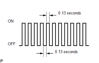
(f) Check that the MIL flashes as shown in the illustration.
NOTICE:
- All DTCs and freeze frame data will be cleared if: 1) the Techstream is used to change the ECM from normal mode to check mode or vice versa; or 2) during check mode, the ignition switch is turned from ON to ACC or off.
- Before changing to check mode, make notes of the DTCs and freeze frame data.
(g) Start the engine. The MIL should turn off after the engine starts.
(h) Simulate the conditions of the malfunction described by the customer.
(i) After simulating the malfunction conditions, use the Techstream to check the DTC and freeze frame data.
 Dtc Check / Clear
DTC CHECK / CLEAR
NOTICE:
When the diagnosis system is changed from normal mode to check mode or vice versa,
all DTCs and freeze frame data recorded in normal mode are cleared. Before changing
m ...
 Fail-safe Chart
FAIL-SAFE CHART
Description
This function minimizes the loss of the Continuously Variable Transaxle (CVT)
system functions when a malfunction occurs in a sensor or solenoid valve.
Fail-safe
(a) ...
Other materials:
Toyota CH-R Service Manual > Power Window Control System: Operation History List
OPERATION HISTORY LIST
NOTICE:
If the vehicle or vehicle controls are operated (for example, during
initial inspection when the vehicle is brought in for repair) before operation
history has been read out and saved, the operation history information could
be lost.
The funct ...
Toyota CH-R Service Manual > Instrument Panel Speaker: Components
COMPONENTS
ILLUSTRATION
*1
FRONT DOOR OPENING TRIM WEATHERSTRIP
*2
FRONT NO. 2 SPEAKER ASSEMBLY
*3
FRONT PILLAR GARNISH ASSEMBLY
*4
NO. 1 INSTRUMENT PANEL SPEAKER PANEL SUB-ASSEMBLY
...
Toyota C-HR (AX20) 2023-2026 Owner's Manual
Toyota CH-R Owners Manual
- For safety and security
- Instrument cluster
- Operation of each component
- Driving
- Interior features
- Maintenance and care
- When trouble arises
- Vehicle specifications
- For owners
Toyota CH-R Service Manual
- Introduction
- Maintenance
- Audio / Video
- Cellular Communication
- Navigation / Multi Info Display
- Park Assist / Monitoring
- Brake (front)
- Brake (rear)
- Brake Control / Dynamic Control Systems
- Brake System (other)
- Parking Brake
- Axle And Differential
- Drive Shaft / Propeller Shaft
- K114 Cvt
- 3zr-fae Battery / Charging
- Networking
- Power Distribution
- Power Assist Systems
- Steering Column
- Steering Gear / Linkage
- Alignment / Handling Diagnosis
- Front Suspension
- Rear Suspension
- Tire / Wheel
- Tire Pressure Monitoring
- Door / Hatch
- Exterior Panels / Trim
- Horn
- Lighting (ext)
- Mirror (ext)
- Window / Glass
- Wiper / Washer
- Door Lock
- Heating / Air Conditioning
- Interior Panels / Trim
- Lighting (int)
- Meter / Gauge / Display
- Mirror (int)
- Power Outlets (int)
- Pre-collision
- Seat
- Seat Belt
- Supplemental Restraint Systems
- Theft Deterrent / Keyless Entry

0.0079